Crack pouring auxiliary equipment for bridge construction

A technology for bridge construction and auxiliary equipment, applied in bridge construction, bridges, bridge parts, etc., can solve the problems of caulk damage, hand injury, high work intensity, etc., and achieve the goals of reducing fatigue strength, convenient and quick operation, and improving efficiency Effect

Active Publication Date: 2022-01-28
武汉船舶职业技术学院
View PDF13 Cites 0 Cited by
  • Summary
  • Abstract
  • Description
  • Claims
  • Application Information

AI Technical Summary

Problems solved by technology

Once the telescopic device of the skew bridge is damaged, it will seriously affect the speed, comfort and safety of driving, and even cause driving safety accidents
[0004] During the construction of existing bridges, it is necessary to inject a caulking agent into the expansion joints of the bridge. After the existing caulking agent is injected into the expansion joints of the bridge, it will bond with the steel plates on both sides of the expansion joints. The sealant has a certain degree of elasticity, so as to meet the needs of expansion and contraction, and at the same time ensure the smoothness of the bridge deck. However, the sealant will be damaged after a certain period of use, which requires maintenance and re-injection of the sealant. When the existing sealant is removed, the residual condensed sealant attached to the surface of the steel plate is often removed with a manual hand-held blade, so that the staff needs to bend down and squat down to operate, and the work intensity is high , and it is easy to cause damage to the hands, which has certain dangers and low work efficiency

Method used


Image

  • Crack pouring auxiliary equipment for bridge construction
  • Crack pouring auxiliary equipment for bridge construction
  • Crack pouring auxiliary equipment for bridge construction

Examples


Embodiment Construction

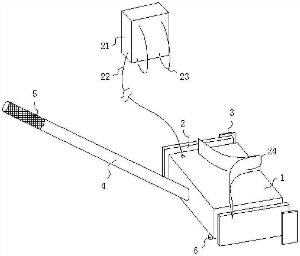
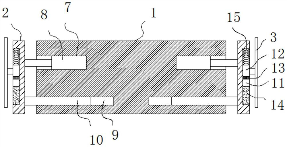
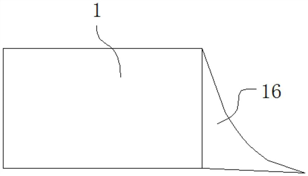
[0026] The following will clearly and completely describe the technical solutions in the embodiments of the present invention with reference to the accompanying drawings in the embodiments of the present invention. Obviously, the described embodiments are only some, not all, embodiments of the present invention.

[0027] In describing the present invention, it should be understood that the terms "upper", "lower", "front", "rear", "left", "right", "top", "bottom", "inner", " The orientation or positional relationship indicated by "outside", etc. is based on the orientation or positional relationship shown in the drawings, and is only for the convenience of describing the present invention and simplifying the description, rather than indicating or implying that the referred device or element must have a specific orientation, so as to Specific orientation configurations and operations, therefore, are not to be construed as limitations on the invention.

[0028] In the description...


PUM


Abstract

The invention belongs to the field of bridge construction, and particularly relates to crack pouring auxiliary equipment for bridge construction; the equipment comprises a fixing block, a handle is fixedly connected to the rear side wall of the fixing block, mounting grooves are formed in the two side walls of the fixing block, and first electric push rods are fixedly mounted in inner cavities of the mounting grooves. The outer end of a piston rod of each first electric push rod is fixedly connected with a connecting plate. The first electric push rods can drive two sets of blades to be adjusted to adapt to the width of an expansion joint, the blades are attached to the inner surface of a steel plate, then an electromagnet is started, the direction of current introduced into the electromagnet is continuously changed, so that the suction force and thrust force on a magnet block can be rapidly and alternately generated; the blades can be driven to quickly move up and down, so that the blades can be attached to the steel plate to quickly remove the bonded joint mixture, the operation is convenient and quick, and compared with manual removal in the past, more labor is saved, the efficiency is remarkably improved, and meanwhile, the adaptability is high.

Description

technical field [0001] The invention relates to the field of bridge construction, in particular to an auxiliary joint filling equipment for bridge construction. Background technique [0002] Bridges generally refer to structures erected on rivers, lakes and seas to allow vehicles and pedestrians to pass smoothly. In order to adapt to the modern high-speed development of the transportation industry, bridges are also extended to buildings that cross mountain streams, poor geology or meet other transportation needs to make traffic more convenient. A bridge is generally composed of a superstructure, a substructure, a support and ancillary structures. The superstructure is also called a bridge span structure, which is the main structure for crossing obstacles; the substructure includes abutments, piers and foundations; Or the force transmission device installed at the supporting place of the bridge abutment; the auxiliary structures refer to the bridge head board, conical slope ...

Claims


Application Information

Patent Timeline
Patent Type & Authority Applications(China)
IPC IPC(8): E01D22/00E01D19/06
CPCE01D22/00E01D19/06Y02E60/10
Inventor 万军万奉頔张昱余靖华田甜刘国武
Owner 武汉船舶职业技术学院
Why Eureka
Try Eureka