
Anchor cable-reinforced soil combined retaining member and construction method thereof

A technology of reinforced soil and components, which is applied in basic structural engineering, excavation, artificial islands, etc., can solve the problems of easy damage to the reinforcement, and achieve the effect of facilitating the production of prefabrication, saving manpower, and avoiding the destruction of the reinforcement.

Active Publication Date: 2022-01-28
山西交通控股集团有限公司吕梁南高速公路分公司
View PDF15 Cites 0 Cited by
  • Summary
  • Abstract
  • Description
  • Claims
  • Application Information

AI Technical Summary

Problems solved by technology

[0005] The present invention overcomes the deficiencies of the prior art, and proposes an anchor cable-reinforced soil combined soil retaining component and its construction method, which solves the problem that the tendons are easily damaged in the existing connection structure

Method used


Image

  • Anchor cable-reinforced soil combined retaining member and construction method thereof
  • Anchor cable-reinforced soil combined retaining member and construction method thereof
  • Anchor cable-reinforced soil combined retaining member and construction method thereof

Examples


Embodiment 1

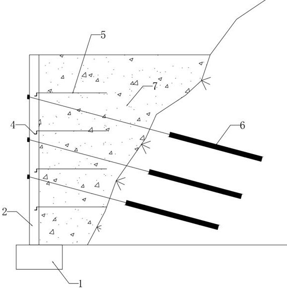
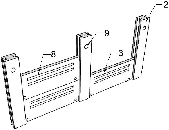
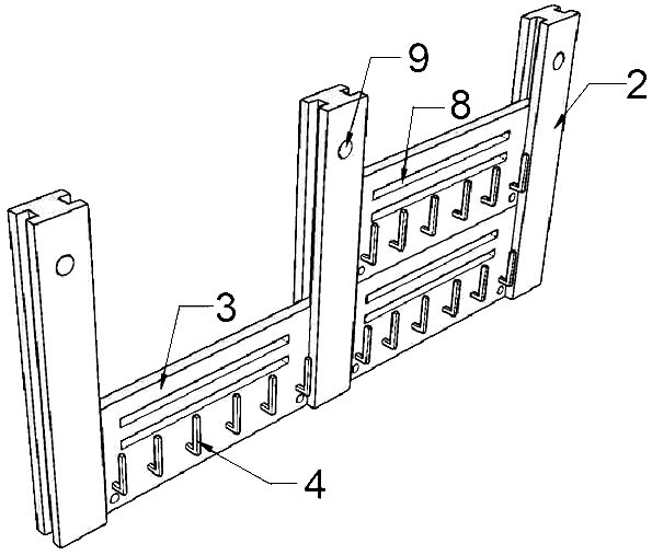
[0039] Refer to attached figure 1 Shown is the anchor cable-reinforced soil combined soil retaining member of this embodiment, including foundation 1, I-shaped column 2, flat wall module 3, steel bar connector 4, geogrid 5, anchor rod 6, filler 7 , drainage channel 8, anchor hole 9. The drainage channel 8 can be provided with a reasonable shape and size as required, and is not limited to a strip channel. refer to Figure 2-Figure 3 , the I-shaped column 2 is clamped and embedded on the foundation 1, and the flat wall module 3 is inserted into the flange of the adjacent I-shaped column 2, referring to Figure 4-Figure 5 , the back of the flat wall module 3 has a steel connector 4, and a drainage channel 8 on the wall; the steel connector 4 is an "L" steel member, and a gap is formed between the steel connector 4 and the flat wall module 3, One end of the geogrid 5 is sleeved on the reinforcement connector 4 and stuck in the gap, so that the reinforcement connector 4 and the ...

Embodiment 2

[0050] In this embodiment, the main structure is the same as that of Embodiment 1, the difference is that the clamping material is a rib-type geogrid, refer to Figure 7 As shown, when the flat wall module 3 is connected with the ribs 11, the ribs 11 can be tied to a horizontal steel bar 10 first, and then the horizontal steel bar 10 can be inserted into a row of "L" shaped steel bars to embed in the gap .

[0051] Concrete construction steps are in the reinforced soil construction process of step 4 in embodiment 1, when the reinforcement material embedded in the back of the wall panel is the rib band 11, the rib band 11 can be bound on a horizontal steel bar 10 earlier, Insert the horizontal steel bar 10 bound with the rib band 11 into the "L" shaped steel bar member. When the soil subsides, the tendon band 11 can move downward along the "L" shaped reinforcement member, which effectively reduces the damage of the reinforcement due to the settlement of the slope.


PUM


Abstract

The invention discloses an anchor cable-reinforced soil combined retaining member and a construction method thereof, and belongs to the technical field of slope support. Tge anchor cable-reinforced soil combined retaining member comprises stand columns and wall surface modules; the stand columns are provided with inserting grooves; the wall surface modules are inserted into the inserting grooves of the stand columns on the two sides; connecting components are arranged on the inner side faces of the wall face modules, and gaps are formed between the connecting components and the wall face modules; one ends of the reinforced materials are arranged on the connecting components in a sleeving mode and clamped in the gaps, and padding is arranged between the upper reinforced materials and the lower reinforced materials; and when the soil body settles, the reinforced materials can move downwards along the connecting components. The side slope bearing capacity and the deformation resistance are remarkably improved, the problem that reinforcement materials in an existing connecting structure are prone to being damaged is solved, and the anchor cable-reinforced soil combined retaining member is suitable for various geological conditions.

Description

technical field [0001] The invention belongs to the technical field of slope support, and in particular relates to an anchor cable-reinforced soil composite retaining component and a construction method thereof. Background technique [0002] The prestressed anchor cable structure refers to the combination of retaining wall and prestressed anchor cable, which can be used separately, in a certain way, and the support structure is formed through the interaction of the anchor cable, retaining wall and slope rock and soil. Jointly bear the rock-soil pressure generated by the landslide thrust or the unloading and relaxation of the slope, so that the slope is in a stable state. Because the prestress can be applied in the anchor cable in advance, the prestressed anchor cable support structure can actively control the relaxation and deformation of the slope. The prestress of the anchor cable makes the unstable sliding mass in a three-dimensional stress state of high confining pressu...

Claims


Application Information

Patent Timeline
Patent Type & Authority Applications(China)
IPC IPC(8): E02D17/20E02D5/76E02D29/02
CPCE02D17/20E02D5/76E02D29/0241
Inventor 谢明星任景瑞陈小艺高孟亮庞冬冬朱孝振
Owner 山西交通控股集团有限公司吕梁南高速公路分公司
Learn More