
Radar signal instantaneous frequency measurement method and device

A radar signal, instantaneous frequency technology, applied in radio wave measurement systems, instruments, etc., can solve the problems of small frequency measurement range, large frequency measurement range, low measurement error, etc., to achieve small measurement range, large frequency measurement range, measurement The effect of low error

Pending Publication Date: 2022-01-28
BEIJING INST OF RADIO METROLOGY & MEASUREMENT
View PDF0 Cites 2 Cited by
  • Summary
  • Abstract
  • Description
  • Claims
  • Application Information

AI Technical Summary

Problems solved by technology

[0004] This application proposes a radar signal instantaneous frequency measurement method and device to solve the problems of small frequency measurement range and low benefit in the prior art. The technical solution of this application makes up for the shortcomings of the above two methods, and the frequency measurement range is large and the measurement error is low.

Method used


Image

  • Radar signal instantaneous frequency measurement method and device
  • Radar signal instantaneous frequency measurement method and device
  • Radar signal instantaneous frequency measurement method and device

Examples


Embodiment Construction

[0031] In order to make the purpose, technical solution and advantages of the present application clearer, the technical solution of the present application will be clearly and completely described below in conjunction with specific embodiments of the present application and corresponding drawings. Apparently, the described embodiments are only some of the embodiments of the present application, rather than all the embodiments. Based on the embodiments in this application, all other embodiments obtained by persons of ordinary skill in the art without making creative efforts belong to the scope of protection of this application.

[0032] The technical solutions provided by various embodiments of the present application will be described in detail below in conjunction with the accompanying drawings.

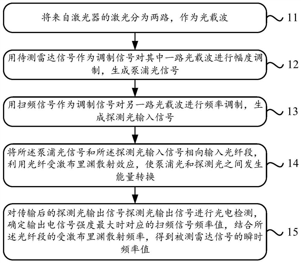
[0033] figure 1 is a schematic diagram of an embodiment of the method of the present application.

[0034] The implementation process of a method for measuring the instantaneous ...


PUM


Abstract

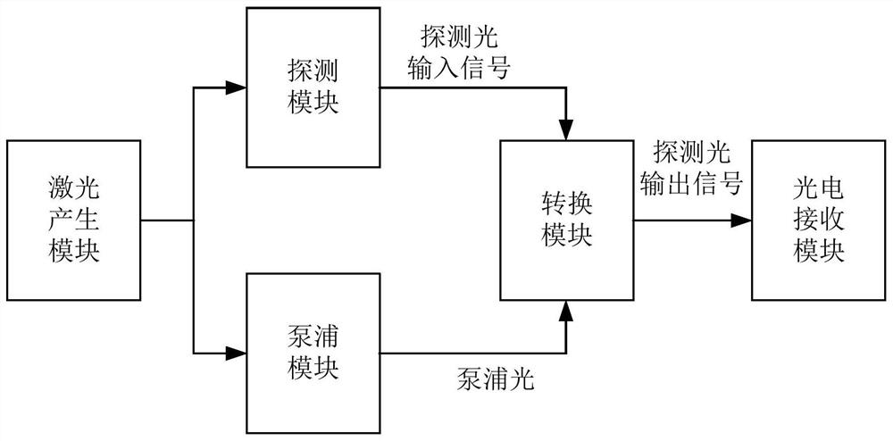
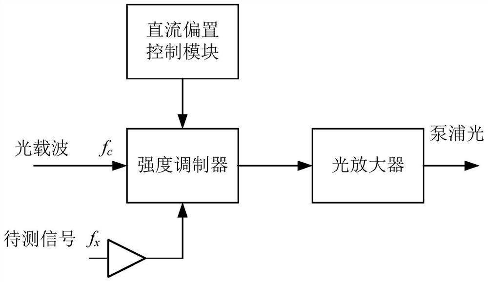
The invention discloses a radar signal instantaneous frequency measurement method and device, and the method comprises the steps: dividing laser from a laser into two paths, and enabling the two paths of laser to serve as optical carriers; taking a radar signal to be measured as a modulation signal to carry out amplitude modulation on one path of optical carrier, and generating a pump optical signal; performing frequency modulation on the other path of optical carrier by using the sweep frequency signal as a modulation signal to generate a probe light input signal; inputting the pump light signal and the probe light input signal into an optical fiber section in opposite directions, and performing energy conversion between the pump light and the probe light by using an optical fiber stimulated Brillouin scattering effect; and performing photoelectric detection on the transmitted probe light output signal, and determining a corresponding frequency sweep signal frequency value when the intensity of the output electric signal is maximum. The problems of small frequency measurement range and low benefit in the prior art are solved.

Description

technical field [0001] The present application relates to the field of radio technology, in particular to a method and device for measuring the instantaneous frequency of radar signals. Background technique [0002] The current radar signal instantaneous frequency measurement method based on the photoelectric combination method mainly includes the radar signal instantaneous frequency measurement method based on the optical fiber dispersion effect and the radar signal instantaneous frequency measurement method based on the four-wave mixing effect. The radar signal instantaneous frequency measurement method based on the optical fiber dispersion effect has a small measurement range for the radar signal frequency, and the measurement error is relatively large. For a single ACF curve measurement frequency value, the measurement error in the low frequency range will be greater. The radar signal instantaneous frequency measurement method based on the four-wave mixing effect has a l...

Claims


Application Information

Patent Timeline
Patent Type & Authority Applications(China)
IPC IPC(8): G01S7/40
CPCG01S7/40
Inventor 刘爽龚鹏伟姜河谢文谌贝
Owner BEIJING INST OF RADIO METROLOGY & MEASUREMENT
Learn More