Computer hardware temperature detection and control device

A temperature control device and temperature detector technology, applied in hardware monitoring, calculation, error detection/correction, etc., can solve problems such as single heat dissipation mode, inconvenient temperature adjustment, and inability to quickly adjust heat dissipation

Inactive Publication Date: 2022-01-28
JILIN AGRI SCI & TECH COLLEGE
View PDF0 Cites 1 Cited by
  • Summary
  • Abstract
  • Description
  • Claims
  • Application Information

AI Technical Summary

Problems solved by technology

[0004] The present invention provides a computer hardware temperature detection and temperature control device, which can effectively solve the problem in the above-mentioned background technology that when cooling the chassis, generally a single cooling method is used, which leads to the inability to quickly dissipate heat according to the actual internal and external environment. And when the internal and external environment is uneven, it is impossible to seal and cool the inside, which makes it inconvenient to adjust the temperature during temperature control. Also in the test, it is impossible to test the load state of the main board, which is prone to instability and unsafe phenomena. , so that the temperature of the electronic components in the chassis cannot be effectively controlled

Method used


Image

  • Computer hardware temperature detection and control device
  • Computer hardware temperature detection and control device
  • Computer hardware temperature detection and control device

Examples


Embodiment

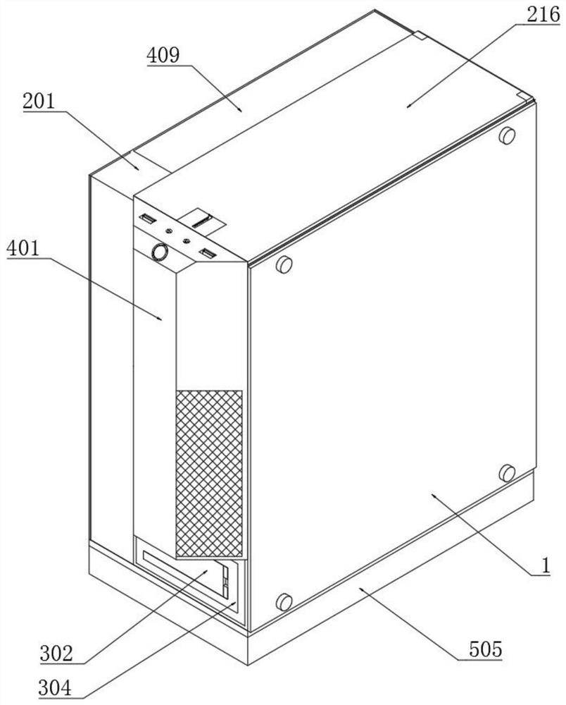
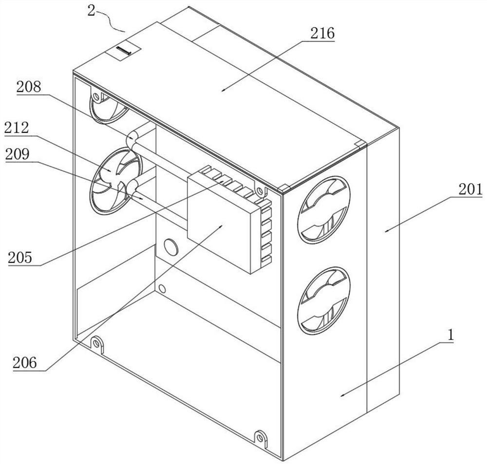
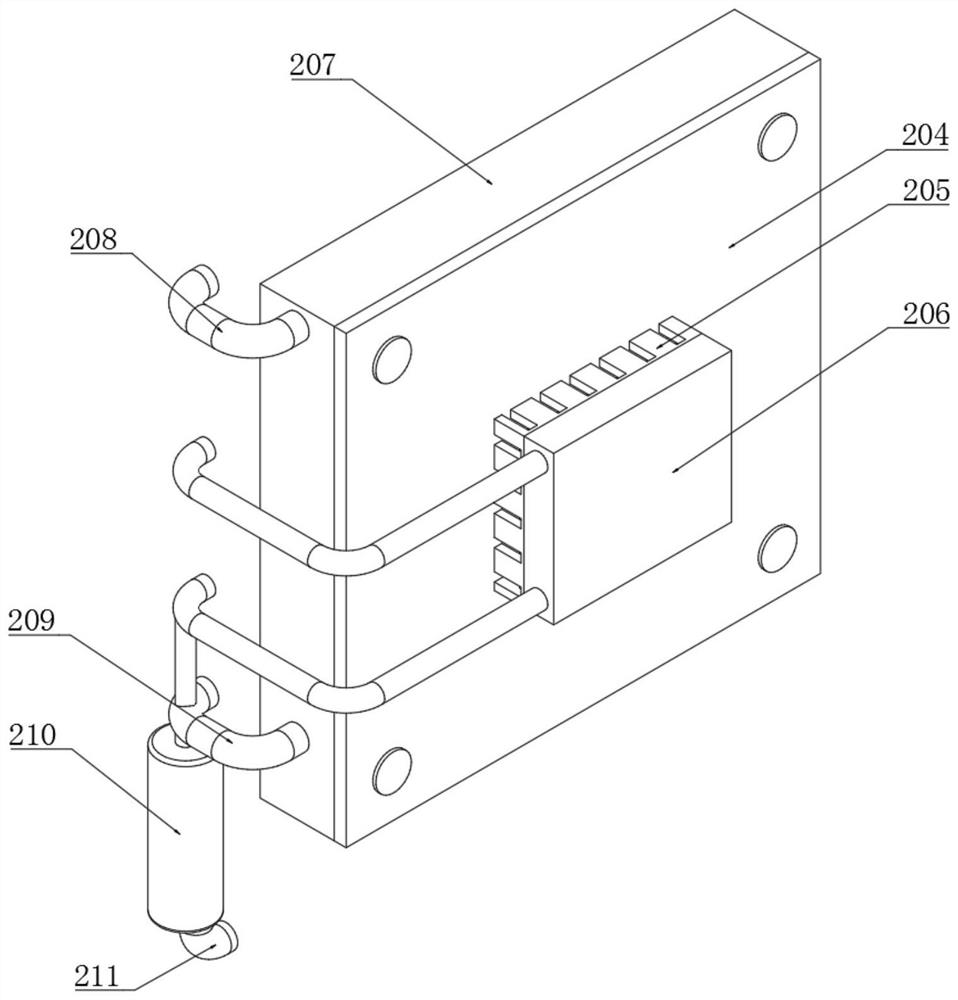
[0045] Example: such as Figure 1-12 As shown, the present invention provides a technical solution, a computer hardware temperature detection and temperature control device, including a housing 1, a temperature control assembly 2 is installed on one side of the housing 1, and the temperature control assembly 2 includes a cooling box 201, a fixed Mounting block 202, temperature detector 203, main board 204, porous heat conduction plate 205, fixed heat conduction box 206, heat absorption box 207, return pipe 208, input pipe 209, booster pump 210, liquid inlet pipe 211, acceleration fan 212, auxiliary Fan 213, protective mesh plate 214, torsion spring 215, blocking protective plate 216, sliding clamping groove 217, pushing spring 218, L-shaped clamping plate 219 and adsorption electromagnet 220;

[0046] A cooling box 201 is fixedly installed at one end of the housing 1, and several fixed installation blocks 202 are installed equidistantly at one end of the inner side of the hous...


PUM

PropertyMeasurementUnit
Maximum rotation angleaaaaaaaaaa

Abstract

The invention discloses a computer hardware temperature detection and temperature control device. The device is characterized in that temperature detectors are mounted at the side end of a fixed mounting block, a fixed heat conduction box sleeves the side end of a porous heat conduction plate, a heat absorption box is fixedly mounted at the position, close to a mainboard, of a shell, backflow pipes penetrate through the tops of one ends of the fixed heat conduction box and the heat absorption box, the water inlet end of an input pipe is fixedly connected with a water outlet end of a booster pump, acceleration fans symmetrically penetrate through the two ends of the shell, an auxiliary fan is installed at the top end of the shell, and a blocking protection plate is welded to one end of a force spring. According to the invention, temperature detection is carried out on different positions in a computer case through the multiple temperature detectors, and heat dissipation is carried out on the interior of computer case through multiple heat exchange and dissipation methods, so rapid cooling can be performed when internal temperature is higher than external temperature and rapid isolation can be carried out when external air temperature is higher than the temperature of the internal case; and thus, the situation that the internal temperature is too high continuously due to interchange of the internal temperature and the external temperature and normal use of a computer is affected is avoided.

Description

technical field [0001] The invention relates to the technical field of computer temperature control, in particular to a computer hardware temperature detection and temperature control device. Background technique [0002] A computer, commonly known as a computer, is a modern electronic computing machine used for high-speed computing. It is a modern intelligent electronic device that can run according to a program and automatically and high-speed process massive data. It is composed of a hardware system and a software system. A computer without any software installed Called bare metal, it can be divided into five categories: supercomputers, industrial control computers, network computers, personal computers, and embedded computers. More advanced computers include biological computers, photonic computers, and quantum computers. [0003] However, at present, when cooling the chassis, a single cooling method is generally used, which leads to the inability to quickly adjust the h...

Claims


Application Information

Patent Timeline
IPC IPC(8): G06F1/20G06F11/30B08B9/087
CPCG06F1/20G06F11/3058B08B9/087
Inventor 姜春风
Owner JILIN AGRI SCI & TECH COLLEGE
Why Eureka
Try Eureka