
Magnetic resonance coil support

A coil support and magnetic resonance technology, which is applied in the field of coil support, can solve the problems of coil damage, thickness reduction, time-consuming and labor-intensive problems, and achieve the effect of improving automation, saving time and effort in operation, and reducing labor intensity

Active Publication Date: 2022-01-28
PEKING UNIV SHENZHEN HOSPITAL
View PDF9 Cites 0 Cited by
  • Summary
  • Abstract
  • Description
  • Claims
  • Application Information

AI Technical Summary

Problems solved by technology

[0003] There are certain deficiencies in the above-mentioned patents. On the one hand, when the device in the above-mentioned patent takes out the coil, the upper box needs to be manually pulled upwards to open the upper box. This process requires human participation and increases the labor of the operator. strength, and it is time-consuming and labor-intensive. On the one hand, only one coil can be placed inside the lower box in the above patent, which cannot accommodate multiple sets of coils. On the other hand, when the upper box is closed in the above patent, the sponge layer is very soft. It is easy to deform, and the thickness becomes smaller after long-term use, which weakens the clamping effect on the coil, and the coil is prone to damage due to shaking. Therefore, we disclose a magnetic resonance coil bracket to meet people's needs

Method used


Image

  • Magnetic resonance coil support
  • Magnetic resonance coil support
  • Magnetic resonance coil support

Examples


Embodiment

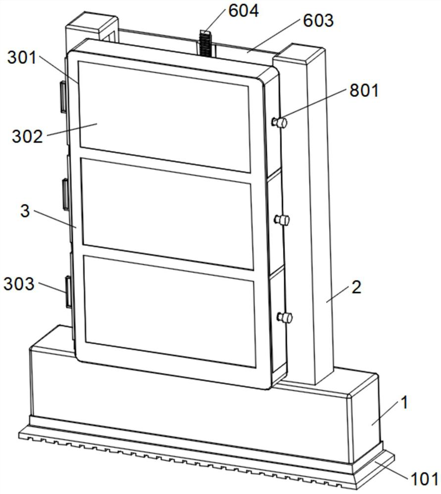
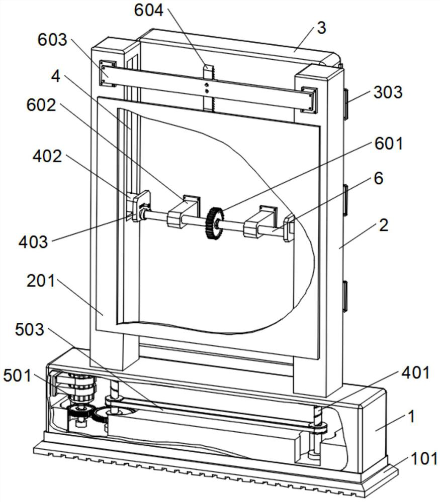
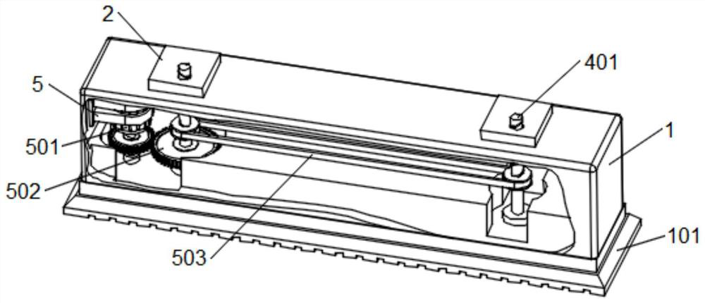
[0038] Example: Reference Figure 1-8 The shown magnetic resonance coil support includes a base 1, a fixed column 2 and a rotating storage box 3. The base 1 is provided with an inner cavity, and the inner cavity of the base 1 is provided with a drive assembly. The upper surface of the base 1 is symmetrical Two groups of fixed columns 2 are fixedly installed, and the rear sides of the two groups of fixed columns 2 are fixedly installed with a rear protection plate 201, and a rotating assembly is arranged between the two groups of fixed columns 2, and each group of fixed columns 2 is internally provided with a lifting assembly. The front side of the column 2 is provided with a rotating storage box 3, and the surface of the rotating storage box 3 is equidistantly provided with three sets of storage grooves 301, and the left side surface of the rotating storage box 3 and the storage groove 301 are all slidably installed with a sliding sealing plate 302, and the sliding sealing plat...


PUM


Abstract

The invention discloses a magnetic resonance coil support, and relates to the technical field of coil supports, the magnetic resonance coil support comprises a base, fixing columns and a rotary storage box, the base is internally provided with an inner cavity, the inner cavity of the base is provided with a driving assembly, and the upper surface of the base is symmetrically and fixedly provided with two groups of fixing columns; a rear protection plate is fixedly installed on the rear sides of the two sets of fixing columns, and a rotating assembly is arranged between the two sets of fixing columns. When a rotating shaft is about to move to the upper end of a fixing column, a driving gear is meshed with the lower end of a driving rack, along with continuous upward movement of the rotating shaft, the driving rack drives the driving gear and drives the rotating shaft to rotate, and finally the rotating storage box can be driven to swing by 90 degrees through the connection effect of a fixing end block; the front face of the rotating storage box faces upwards, a manual pulling mode adopted in the prior art is replaced, the labor intensity of an operator is reduced to a certain degree, the overall automation degree of the device is improved, operation is easy, and time and labor are saved.

Description

technical field [0001] The invention relates to the technical field of coil supports, in particular to a magnetic resonance coil support. Background technique [0002] With reference to the Chinese patent whose patent number is CN212872864U, it discloses a magnetic resonance coil support, including a support mechanism, the support mechanism includes two vertically parallel support rods, and the bottom ends of the support rods are fixedly connected with a fixed plate , the side wall of the support rod is provided with a chute, and the side wall of the support rod is located at the top of the chute and provided with an outlet groove. In the utility model, through the setting of the chute, the slider and the round rod, it is convenient to accommodate the storage mechanism and reduce the occupied space when idle, and through the setting of the placement cavity, the power supply part of the coil is placed in the placement cavity to avoid The power part of the power supply squeez...

Claims


Application Information

Patent Timeline
Patent Type & Authority Applications(China)
IPC IPC(8): H01F5/02
CPCB65D25/20B65D25/005B65D25/101B65D81/05B65D2585/86Y02A90/30
Inventor 邓灵波成官迅
Owner PEKING UNIV SHENZHEN HOSPITAL
Learn More