Connecting structure for series connection of high-capacity single batteries
A single battery and connection structure technology, applied to structural parts, battery pack parts, circuits, etc., can solve problems that affect installation efficiency and installation difficulties, and achieve the effects of material saving, stable and reliable connection, and simple and convenient operation
- Summary
- Abstract
- Description
- Claims
- Application Information
AI Technical Summary
Problems solved by technology
Method used
Image
Examples
Embodiment 1
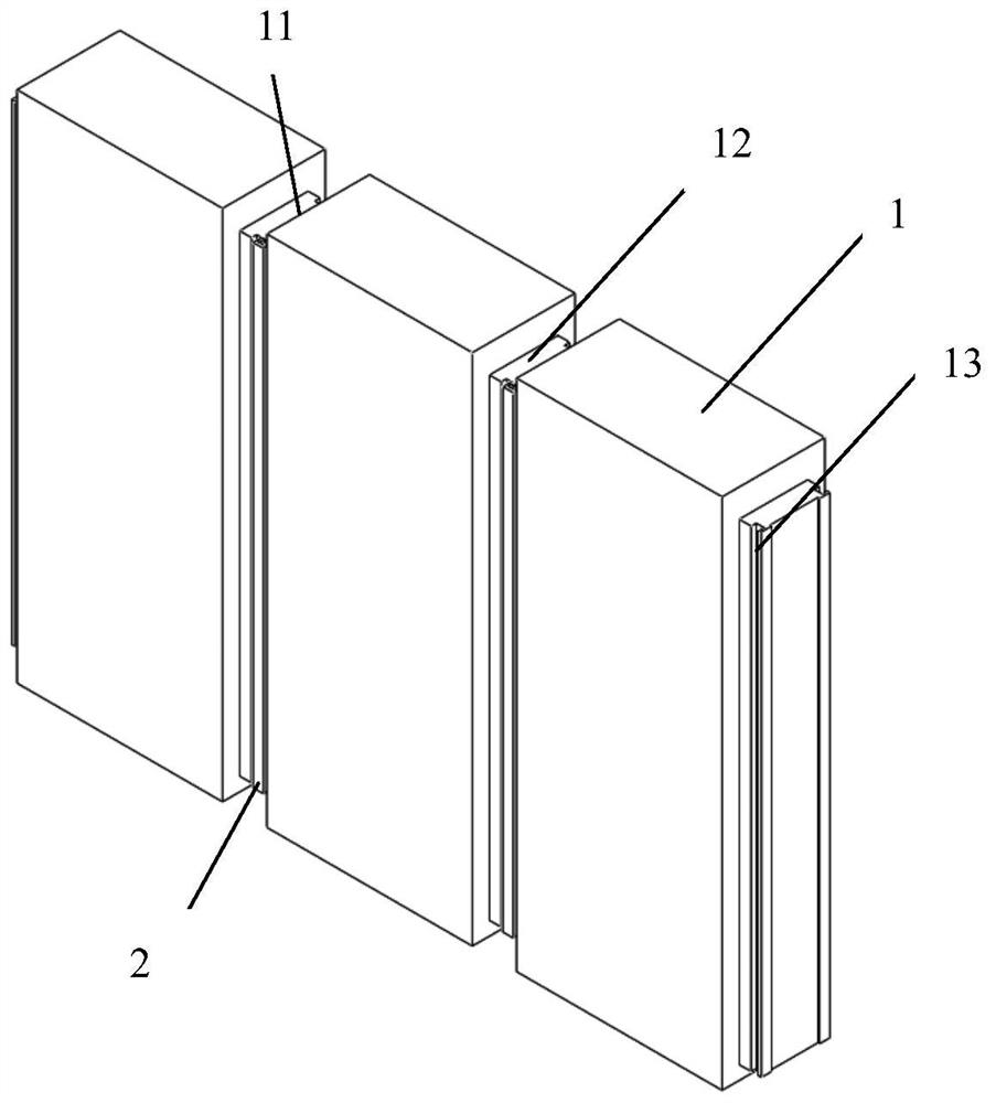
[0053] Such as figure 1 , figure 2 , image 3 As shown, the connection structure of the large-capacity single cells 1 connected in series in this embodiment is formed by connecting three groups of large-capacity single cells 1 in series, and the positive current collecting posts 11 and the negative current collecting posts 12 of the three groups of single cells 1 They are located on two opposite sides of the shell of the large-capacity battery. The cross-section of the current collecting column is rectangular, and part of the current collecting column leaks out of the shell and is insulated and sealed with the shell.
[0054] To further illustrate, grooves 13 are respectively processed on the front and rear panels of the positive current collecting column 11 and the negative current collecting column 12 of each single battery 1, and the grooves 13 are arranged along the positive electrode current collecting column 11 and the negative electrode current collecting column. The...
Embodiment 2
[0056] The specific implementation of this embodiment is based on Embodiment 1, and the difference from Embodiment 1 is that, as shown in 4, this embodiment relates to a connection structure in which large-capacity single batteries 1 are connected in series. The high-capacity single battery 1 is composed of three sets of high-capacity single batteries 1 connected in series. The positive and negative current collectors 12 of the three sets of single batteries 1 are located on the two opposite sides of the shell of the large-capacity battery. The cross-section is rectangular, and part of the current collecting column leaks out of the shell and is insulated and sealed with the shell. U-shaped embedded grooves 15 are respectively opened on the connecting surfaces of the positive electrode current collecting column 11 and the negative electrode current collecting column 12 corresponding to two adjacent single cells 1, so that the two adjacent single cells 1 The U-shaped embedded gr...
Embodiment 3
[0059] The specific implementation of this embodiment is on the basis of embodiment 1, and the difference with embodiment 1 is: as Figure 5 , Figure 6 As shown, five pairs of rectangular grooves 13 are respectively arranged on the front panel and the rear panel of the positive electrode current collecting post 11 and the negative electrode current collecting post 12 of each single battery 1 of the present embodiment, and the grooves 13 are separated from the two single battery cells. The horizontal spacing of the current collecting posts of 1 is about 15 cm. Through holes 14 are respectively opened on the inner wall of the groove 13 and the panels of the corresponding current collecting posts of the two single cells 1. When the first battery When the negative electrode current collecting column 12 of the first battery is connected in series with the positive electrode current collecting column 11 of the second battery, the five pairs of grooves 13 on the front panel of the t...
PUM
 Abstract
Description
Claims
Application Information
 - R&D
- Intellectual Property
- Life Sciences
- Materials
- Tech Scout
- Unparalleled Data Quality
- Higher Quality Content
- 60% Fewer Hallucinations
Browse by: Latest US Patents, China's latest patents, Technical Efficacy Thesaurus, Application Domain, Technology Topic, Popular Technical Reports.
© 2025 PatSnap. All rights reserved.Legal|Privacy policy|Modern Slavery Act Transparency Statement|Sitemap|About US| Contact US: help@patsnap.com


