
Power system automatic control intelligent deicing device and deicing method

A power system and intelligent technology, which is applied in the installation of cables, electrical components, overhead installation, etc., can solve the problems of long heating time, increased line weight, and large damage to high-voltage transmission lines, so as to achieve continuous and stable heating and prevent idling transmission , The effect of firm and stable contact

Inactive Publication Date: 2022-01-28
LISHUI UNIV
View PDF0 Cites 0 Cited by
  • Summary
  • Abstract
  • Description
  • Claims
  • Application Information

AI Technical Summary

Problems solved by technology

[0003] With the frequent occurrence of extreme weather, especially extreme weather such as heavy snowfall and freezing rain, it will cause great damage to high-voltage transmission lines. Toughness and tensile strength test technology is large, and every time it happens is a weather change within the scope, if it is not cleaned up in time, it will affect the safety of the circuit transmission equipment, but now it is mostly cleaned by manpower and wire transformer temperature rise. The efficiency of manual cleaning is low, and a specific voltage needs to be applied to the wire to increase the temperature of the wire, which blocks the normal transmission and use of the circuit, and the heating effect on the melting of the cylindrical ice shell is poor, and the heating time is long. The temperature rise of the cable is uncontrollable, and there are many obstacles to the actual operation

Method used


Image

  • Power system automatic control intelligent deicing device and deicing method
  • Power system automatic control intelligent deicing device and deicing method
  • Power system automatic control intelligent deicing device and deicing method

Examples


Embodiment Construction

[0030] The following will clearly and completely describe the technical solutions in the embodiments of the present invention with reference to the accompanying drawings in the embodiments of the present invention. Obviously, the described embodiments are only some, not all, embodiments of the present invention. Based on the embodiments of the present invention, all other embodiments obtained by persons of ordinary skill in the art without making creative efforts belong to the protection scope of the present invention.

[0031] In describing the present invention, it is to be understood that the terms "center", "upper", "lower", "front", "rear", "left", "right", "vertical", "horizontal", The orientations or positional relationships indicated by "top", "bottom", "inner", "outer", etc. are based on the orientations or positional relationships shown in the drawings, and are only for the convenience of describing the present invention and simplifying the description, rather than in...


PUM


Abstract

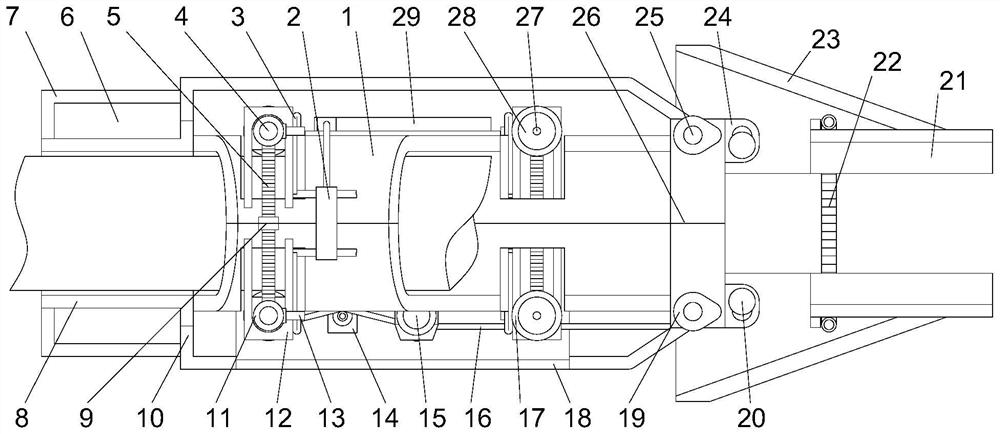
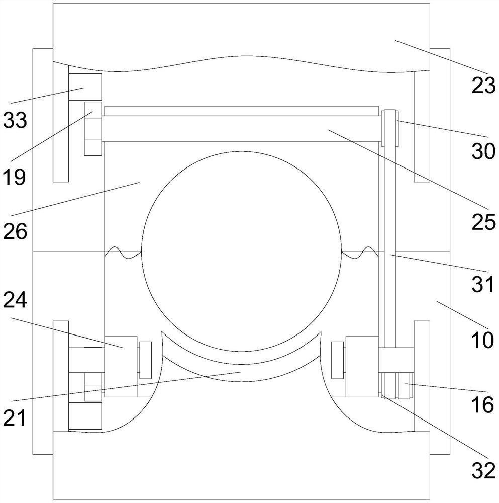
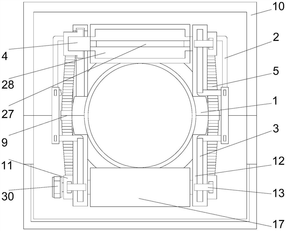
The invention discloses a power system automatic control intelligent deicing device and a deicing method. The power system automatic control intelligent deicing device comprises a middle pipe, a shell, a neck bush, an icebreaking assembly, a pressing assembly, an anti-sticking roller and a motor, wherein the neck bush is fixedly installed at the left end of the middle pipe, the shell is installed on the outer side of the middle pipe in a sleeving mode, the icebreaking assembly is fixedly installed at the right end of the middle pipe, the middle pipe, the neck bush, the icebreaking assembly and the shell are divided into an upper part and a lower part which are symmetrical, the joint positions of the rear ends of the shell are connected through a hinge, the front ends of the shell are detachably connected, and self-adaptive openings are formed in the upper side wall and the lower side wall of the middle pipe. The power system automatic control intelligent deicing device is reasonable in structural design, flexible in structure and convenient to disassemble and assemble, a tensioner is matched with the pressing assembly, firm and stable contact between the anti-sticking roller and a cable can be guaranteed, idling transmission is prevented, ice can be tilted and broken off through the ice breaking assembly, automatic and continuous ice removing operation is achieved, the anti-sticking roller is arranged, equipment is prevented from being frozen on the cable in a low-temperature state, and therefore heating is continuous and stable.

Description

technical field [0001] The invention relates to the field of electric equipment maintenance, in particular to a power system automatic control intelligent deicing device and a deicing method. Background technique [0002] The electricity generated by the power plant is not only used by nearby people, but also transmitted to distant places to meet more needs. These electricity cannot be transmitted directly through ordinary wires, but are transmitted by high-voltage transmission lines. Generally, the transmission voltage below 220 kV is called high-voltage transmission, and the transmission voltage of 330 to 765 kV is called ultra-high voltage transmission. 1000 kV The above transmission voltage is called UHV transmission. [0003] With the frequent occurrence of extreme weather, especially extreme weather such as heavy snowfall and freezing rain, it will cause great damage to high-voltage transmission lines. Toughness and tensile strength test technology is large, and ever...

Claims


Application Information

Patent Timeline
Patent Type & Authority Applications(China)
IPC IPC(8): H02G7/16H02G1/02
CPCH02G7/16H02G1/02
Inventor 王野毛亮亮吴晓飞黄晓艳樊楼英李建峰凌锋
Owner LISHUI UNIV
Learn More