
Non-contact permanent magnet supporting device

A support device, non-contact technology, used in electromechanical devices, permanent magnet clutches/brakes, electrical components, etc., can solve problems such as no better solutions, and achieve optimized process operation and final product yield, no The effect of friction damage and avoiding secondary pollution

Pending Publication Date: 2022-01-28
TSINGHUA UNIV
View PDF5 Cites 0 Cited by
  • Summary
  • Abstract
  • Description
  • Claims
  • Application Information

AI Technical Summary

Problems solved by technology

As of now, there is no better solution

Method used


Image

  • Non-contact permanent magnet supporting device
  • Non-contact permanent magnet supporting device
  • Non-contact permanent magnet supporting device

Examples


Embodiment Construction

[0028] Embodiments of the present invention will be described below with reference to the accompanying drawings. Those skilled in the art would recognize that the described embodiments can be modified in various ways or combinations thereof without departing from the spirit and scope of the invention. Accordingly, the drawings and description are illustrative in nature and not intended to limit the scope of the claims. Also, in this specification, the drawings are not drawn to scale, and like reference numerals denote like parts.

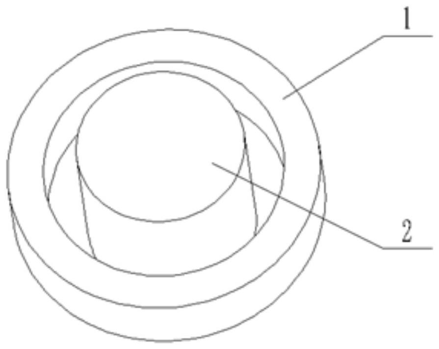
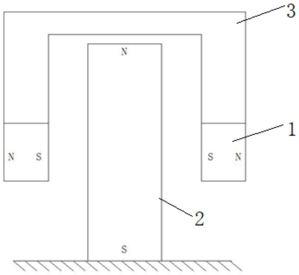
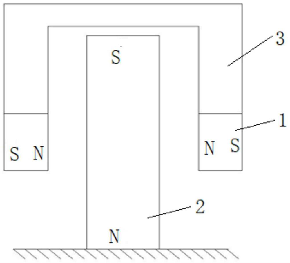
[0029] figure 1 is a three-dimensional view of the non-contact permanent magnetic support device of the embodiment of the present invention, figure 2 It is a two-dimensional cross-sectional view of a form of the non-contact permanent magnetic support device of the embodiment of the present invention. Such as figure 1 , figure 2 As shown, the non-contact permanent magnet support device of this embodiment includes a mover 1, a stator 2, and a s...


PUM


Abstract

The invention discloses a non-contact type permanent magnet supporting device which comprises a stator, a rotor and asupporting body; the stator is a vertical cylindrical permanent magnet, the stator is magnetized in the axis direction, the upper portion of the stator is a first magnetic pole, and the lower portion of the stator is a second magnetic pole opposite to the first magnetic pole; the rotor is an annular permanent magnet, the rotor is coaxially arranged on the periphery of the stator, the rotor is magnetized in the radial direction, the outer side circumference of the rotor is a first magnetic pole, and the inner side circumference of the rotor is a second magnetic pole opposite to the first magnetic pole; and the supporting body is fixedly connected with the rotor and is suspended above the stator. According to the invention, the non-contact mode is suitable for the rotating motion of the wafer, and particles, vibration and noise caused by contact work are avoided; and a certain gap exists when the rotor and the stator are installed, friction damage is avoided in the relative rotation process of the rotor and the stator, the service life of the rotor is greatly prolonged, and secondary pollution of fine impurities to a wafer application scene is avoided.

Description

technical field [0001] The invention relates to a support structure, in particular to a non-contact permanent magnet support device, which is mainly used in the technical field of precision manufacturing equipment. Background technique [0002] At present, many industrial equipment need to drive components to perform multi-degree-of-freedom movements and precisely position them, such as silicon wafer stages and mask stages in lithography machines, and print heads in 3D printers. For the multi-degree-of-freedom movement and its precise positioning, support structures are required. In some occasions where motion accuracy is not high, multiple sets of linear guide rails or ball screw transmission structures are often used to superimpose in different directions to achieve multi-degree-of-freedom motion. This type of structure will produce particles due to mechanical friction during work, which will affect the vacuum. cleanliness. In many ultra-precision workbenches, air bearin...

Claims


Application Information

Patent Timeline
IPC IPC(8): H02K49/10
CPCH02K49/106Y02T10/64
Inventor 张鸣朱煜成荣刘相波
Owner TSINGHUA UNIV
Learn More