Drill

A drill bit and main body technology, used in twist drills, drilling tool accessories, drilling/drilling equipment, etc., can solve problems such as increased resistance, clogging of chips, breakage of the main body of the drill bit, etc., to prevent breakage and improve truncation. Effect

Pending Publication Date: 2022-01-28
MITSUBISHI MATERIALS CORP
View PDF2 Cites 0 Cited by
  • Summary
  • Abstract
  • Description
  • Claims
  • Application Information

AI Technical Summary

Problems solved by technology

[0007] Therefore, it is difficult to cut off the chips generated by the sharpening edge with a small curl, and the chips are clogged in the chip flutes, resulting in increased resistance, which may cause breakage of the drill body especially in small-diameter deep hole machining.
In addition, the chips generated by the sharpening edge tend to extend in the grinding direction connecting the most axially recessed points on the bottom surface of the sharpening portion. It is easy to extend in the normal direction of the chip, so these chips interfere with each other, and it may still be difficult to cut the chip with a small curl

Method used


Image

  • Drill
  • Drill
  • Drill

Examples


Embodiment Construction

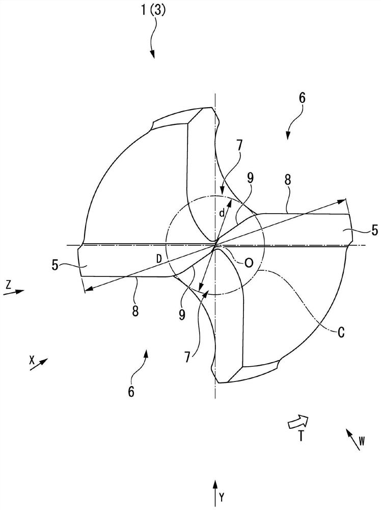
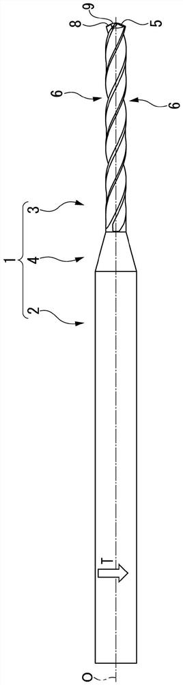
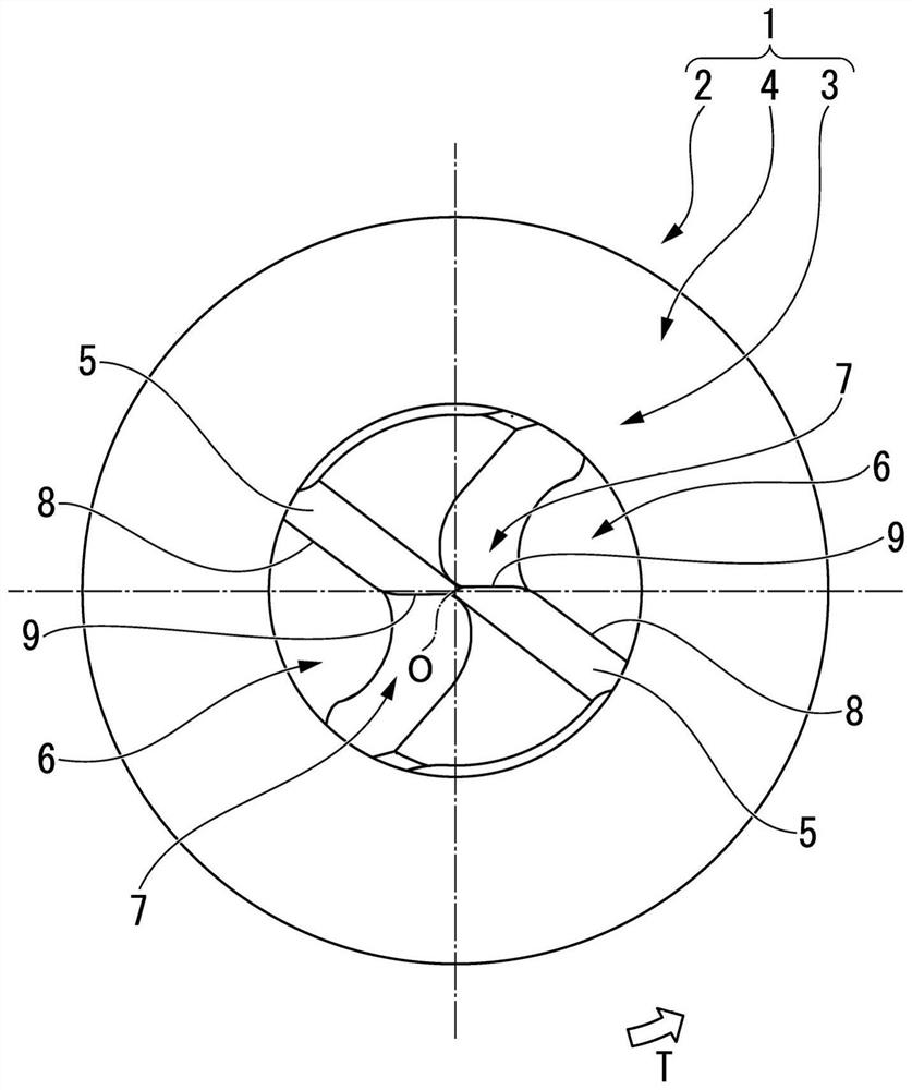
[0035] Figure 1 to Figure 11 An embodiment of the present invention is shown. In the present embodiment, the drill body 1 is integrally formed of a hard metal material such as cemented carbide in a multi-stage cylindrical shape centered on the axis O. The large-diameter rear end of the drill body 1 ( figure 2 and Figure 4 , Figure 6 ~ Figure 10 Middle is the left part. Figure 5 The center is the upper right side part) is set to maintain the cylindrical shank 2, and the small diameter front end ( figure 2 and Figure 4 Middle is the right part, Figure 6 ~ Figure 10 Middle is the right part. Figure 5 The center is the lower left part) as the cutting edge portion 3 .

[0036] In this type of drill, the shank 2 is held by the spindle of the machine tool, the drill body 1 is sent out to the front end side in the direction of the axis O while rotating around the axis O in the drill rotation direction T, and the cutting edge 3 drills the material to be cut. hole machin...


PUM


Abstract

In this drill: a main cutting blade (8) is formed on a tip side ridge section of a chip discharge groove (6) formed on the tip outer periphery of a drill body (1); a thinning blade (9) is formed on a tip side ridge section of a thinning section (7) having recessed a groove shape formed in the tip inner periphery of the chip discharge groove (6); when viewed from the twist direction of the chip discharge groove, the radius of the inscribing circle of the chip discharge groove falls within the range of 0.3xD2 to 0.7xD2 with respect to the diameter D2 of a second circle; in the thinning section (7), the radius (R2) of a thinning inscribing circle (C6) falls within the range of 0.3xd to 0.7xd with respect to the core thickness (d) when viewed in the thinning direction; and the ratio A / B between the ratio A=R1 / D2 of a radius R1 to the diameter D2 and the ratio B=R2 / d of the radius (R2) to the core thickness (d) fall within the range of 0.8 to 1.25.

Description

technical field [0001] The present invention relates to a drill in which a chip flute is formed on the outer periphery of the front end portion of a drill body that rotates around an axis in the drill rotation direction. The main cutting edge is formed on the front end side edge of the drill body on the wall surface of the chip flute facing the drill rotation direction, and on the On the inner peripheral portion of the front end of the chip flute, a groove-shaped grinding portion extending toward the inner peripheral side as it approaches the front end side of the drill body is formed. A sharpening edge connected to the inner peripheral side of the main cutting edge is formed on the front end side edge of the drill body. [0002] This application claims priority based on Patent Application No. 2019-127145 filed in Japan on July 8, 2019, the contents of which are incorporated herein. Background technique [0003] As a drill bit having such a sharpening edge, for example, a ...

Claims


Application Information

Patent Timeline
Patent Type & Authority Applications(China)
IPC IPC(8): B23B51/02
CPCB23B51/02B23B2251/043B23B2251/14B23B2251/408B23B2251/04B23B2251/182B23B51/06
Inventor 佐藤晃木村友树
Owner MITSUBISHI MATERIALS CORP
Why Eureka
Try Eureka