
Side beam machining die and forming process

A technology for processing molds and side beams, which is applied in the field of aircraft side beam processing equipment, can solve the problems of difficult to improve product surface processing accuracy, difficult to ensure positioning accuracy, easy to damage product surface, etc., to achieve easy demoulding, high positioning accuracy, and mold The effect of easy assembly

Pending Publication Date: 2022-02-01
天津爱思达新材料科技有限公司
View PDF0 Cites 0 Cited by
  • Summary
  • Abstract
  • Description
  • Claims
  • Application Information

AI Technical Summary

Problems solved by technology

Although in the prior art, the mold is designed separately in the height direction or the width direction, it is difficult to guarantee the positioning accuracy when assembling such a processing mold, and it is difficult to improve the surface processing accuracy of the product, and it is even easy to affect the performance or impact due to large processing errors. Assembly, especially after the product is thermally cured, it is difficult to demould, and the product surface is easily damaged during demoulding

Method used


Image

  • Side beam machining die and forming process
  • Side beam machining die and forming process
  • Side beam machining die and forming process

Examples


Embodiment Construction

[0045] It should be noted that, in the case of no conflict, the embodiments of the present invention and the features in the embodiments can be combined with each other.

[0046] In describing the present invention, it should be understood that the terms "center", "longitudinal", "transverse", "upper", "lower", "front", "rear", "left", "right", The orientations or positional relationships indicated by "vertical", "horizontal", "top", "bottom", "inner", "outer", etc. are based on the orientation or positional relationships shown in the drawings, and are only for the convenience of describing the present invention Creation and simplification of description, rather than indicating or implying that the device or element referred to must have a specific orientation, be constructed and operate in a specific orientation, and therefore should not be construed as limiting the invention. In addition, the terms "first", "second", etc. are used for descriptive purposes only, and should no...


PUM


Abstract

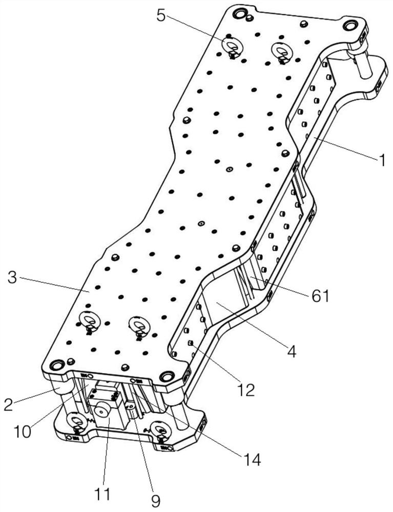
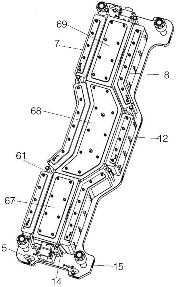
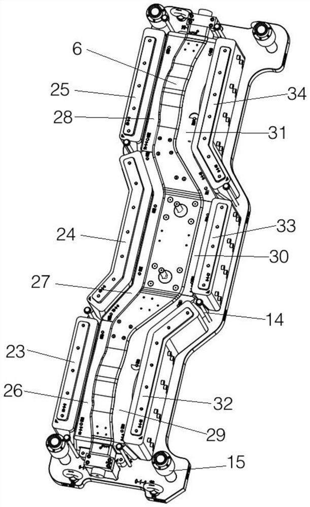
The invention provides a side beam machining mold which comprises a foundation structure, wherein the foundation structure comprises a base plate and a top plate installed on the base plate through a guide supporting unit, and a mold assembly is installed between the base plate and the top plate; the mold assembly comprises an integrated core mold, a split left forming mold, a split right forming mold, a split lower forming mold and a split upper forming mold; the top plate, the base plate and all the outer end molds are provided with a plurality of pressing adjusting pieces in allusion to the corresponding forming molds; and after the paved prepreg is thermally cured, a product shape limited by the inner side forming surfaces of the upper, lower, left and right forming molds is obtained. The side beam machining mold is reasonable in structural design, the forming molds and the outer end molds in the mold assembly are of a combined structural design, machining and manufacturing are more convenient, the mold assembly is high in positioning precision, and the workpiece forming quality is good.

Description

technical field [0001] The invention belongs to the technical field of aircraft side beam processing equipment, and in particular relates to a side beam processing mold and a forming process. Background technique [0002] Although the prepreg autoclave process is currently a more commonly used composite material forming process, in the existing technology, for special-shaped long beam members with complex structural dimensions, it is usually composed of an upper mold, a lower mold, and left and right sliders. Process from the mold, and design profiling structures on the upper mold, lower mold and the inner wall of the slider corresponding to the structure of each part of the product to adapt to the special shape of the workpiece surface. Although in the prior art, the mold is designed separately in the height direction or the width direction, it is difficult to guarantee the positioning accuracy when assembling such a processing mold, and it is difficult to improve the surfa...

Claims


Application Information

Patent Timeline
IPC IPC(8): B29C70/34B29C70/54B29C33/30B29L31/30
CPCB29C70/345B29C70/54B29C33/30B29L2031/3076
Inventor 高岩杨大鹏沈月贾金荣
Owner 天津爱思达新材料科技有限公司
Features
  • Generate Ideas
  • Intellectual Property
  • Life Sciences
  • Materials
  • Tech Scout
  • Unparalleled Data Quality
  • Higher Quality Content
  • 60% Fewer Hallucinations
Learn More