Load assembling mechanism and spatial load unfolding and folding device

A technology of assembling mechanism and load, which is applied in fixed devices, motor vehicles, mechanical equipment, etc., can solve the problems of difficult replacement, long-term scalability, and replaceable loads, etc., and achieves convenient replacement, good maintainability, and environmental adaptability. strong effect

Active Publication Date: 2022-02-01
TECH & ENG CENT FOR SPACE UTILIZATION CHINESE ACAD OF SCI
View PDF8 Cites 2 Cited by
  • Summary
  • Abstract
  • Description
  • Claims
  • Application Information

AI Technical Summary

Problems solved by technology

[0004] At present, space science experiment loads are generally installed directly on the ground on the launch platform, and are f

Method used


Image

  • Load assembling mechanism and spatial load unfolding and folding device
  • Load assembling mechanism and spatial load unfolding and folding device
  • Load assembling mechanism and spatial load unfolding and folding device

Examples


Embodiment 1

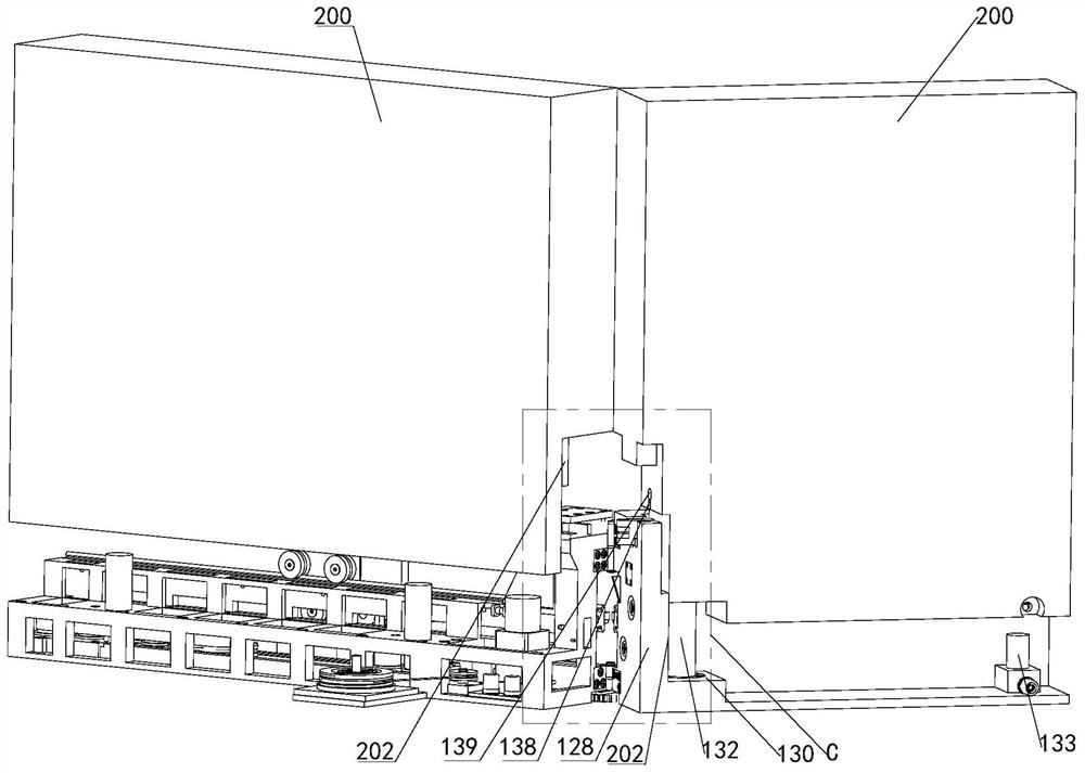
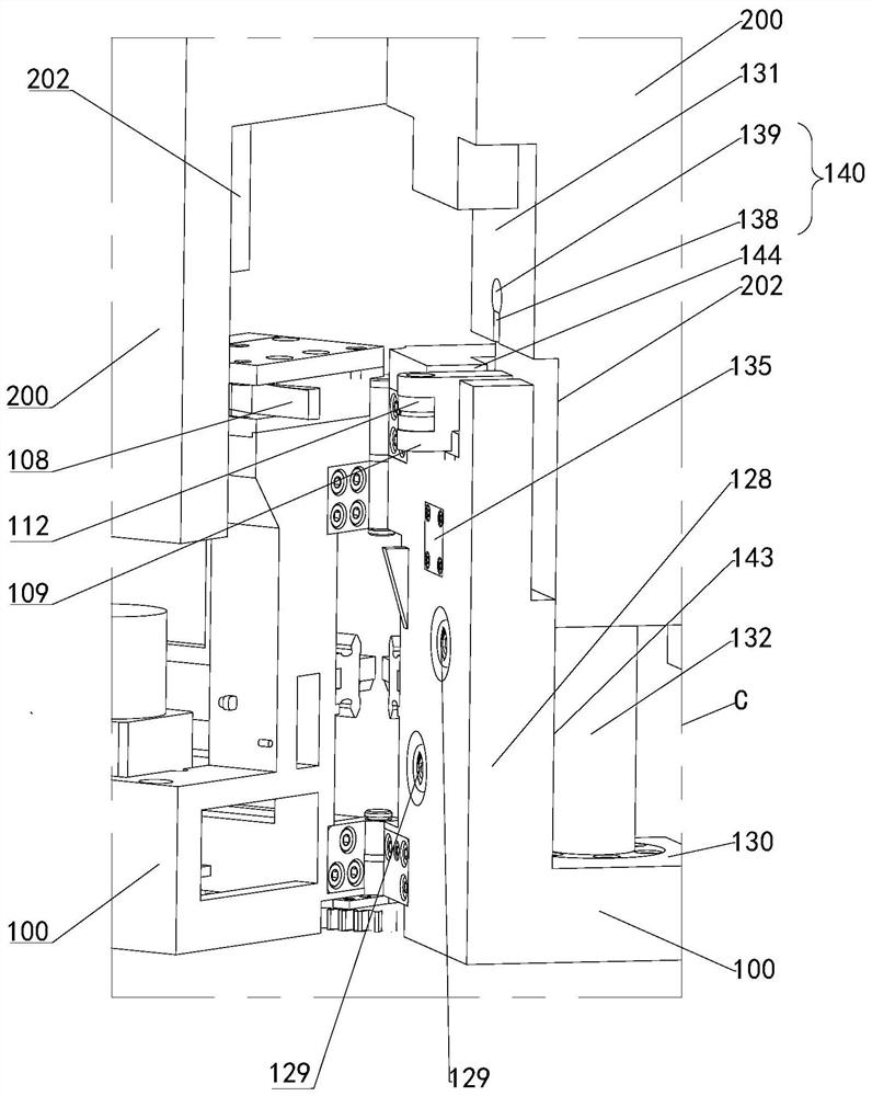
[0045] Such as Figure 1 to Figure 7 As shown, a load assembly mechanism of this embodiment includes a load body 200 and an unfolding platform 100, one side of the unfolding platform 100 is provided with a first stepped structure 124, and the horizontal stepped surface 130 of the first stepped structure 124 There is a guide post on it, and one end of the unfolding platform 100 is provided with a limit wall 128, and the limit wall 128 is provided with a captive screw 129, and the limit wall 128 is provided with an elastic limit piece 145; The bottom side of the load body 200 is provided with a second stepped structure 201 adapted to the first stepped structure 124, and the horizontal stepped surface 130 of the second stepped structure 201 is provided with a guide adapted to the guide column. hole, the bottom end surface of the load body 200 is provided with a limit slot 140 and a screw hole adapted to the elastic limit member 145 .

[0046] Such as Figure 6 and Figure 7 As...

Embodiment 2

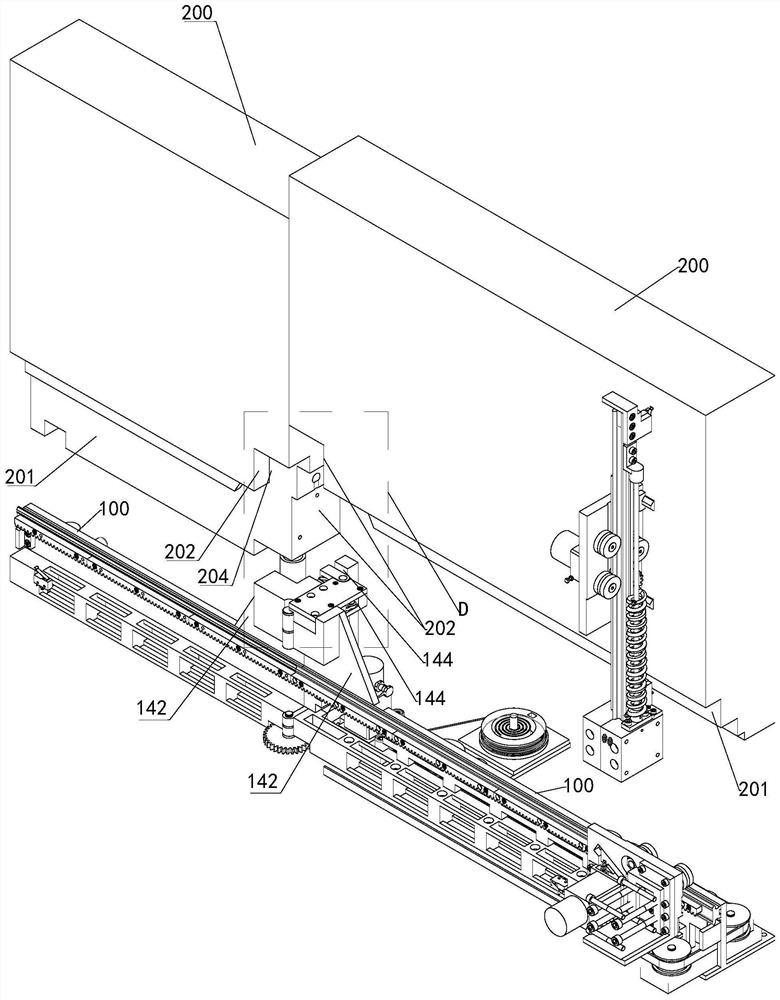
[0055] Such as Figure 8 ~ Figure 11 As shown, a space load deployment device of this embodiment includes the load assembly mechanism described in Embodiment 1, and also includes a deployment drive mechanism and a locking mechanism, and at least two of the deployment platforms 100 are hinged sequentially through hinges 122 The power part of the unfolding drive mechanism is installed on one of the two adjacent unfolding platforms 100, and the transmission gear 104 of the unfolding drive mechanism is rotatably connected to the hinges 122 of the two adjacent unfolding platforms 100. and connected with another deployment platform 100; the locking mechanism includes a latch 125 and a locking assembly 126, and the latch 125 and locking assembly 126 are respectively installed on two adjacent deployment platforms 100 The upper end face of the limiting wall 128; the power part of the unfolding drive mechanism is connected with the transmission gear 104 and drives the transmission gear ...


PUM


Abstract

The invention relates to a load assembling mechanism and a spatial load unfolding and folding device.The load assembling mechanism comprises a load body and an unfolding platform, a first step structure is arranged on one side of the unfolding platform, a guide column is arranged on the horizontal step surface of the first step structure, a limiting wall is arranged at one end of the unfolding platform, and a captive screw is arranged on the limiting wall; an elastic limiting piece is arranged on the limiting wall; and a second step structure matched with the first step structure is arranged on one side of the bottom of the load body, a guide hole matched with the guide column is formed in the horizontal step surface of the second step structure, and a limiting groove matched with the elastic limiting piece and a screw hole are formed in the end surface of one end of the bottom of the load body. The load body and the unfolding platform are stably and reliably assembled, the guide columns are used for guiding and positioning, the elastic limiting pieces are used for limiting, finally the captive screw is used for locking and positioning, the load body is convenient and reliable to disassemble and assemble, on-orbit replacement is convenient, and the requirements of long-term extensible and replaceable loads can be met.

Description

technical field [0001] The invention relates to the related technical field of space load assembly, in particular to a load assembly mechanism and a space load unfolding and retracting device. Background technique [0002] With the development of space science and space technology and the continuous exploration of space by human beings, more and more space experiments need to be carried out. Especially with the completion of the space station and the explosive growth of the number of satellite launches, the types of space motion devices that space science experiment loads need to rely on are developing in the direction of diversification, basicity, long life, and scalability. Space launch missions have the characteristics of shortage of launch volume, launch weight, power supply, and communication resources. The space environment has environmental characteristics such as high and low temperature alternating, high vacuum, strong radiation, and space debris impact. The type a...

Claims


Application Information

Patent Timeline
IPC IPC(8): B64G1/22F16B1/02F16C11/04F16C11/10
CPCB64G1/222F16C11/04F16C11/10F16B1/02
Inventor 刘立坤王珂张璐张聚乐王绍坤盛强乔志宏吕从民
Owner TECH & ENG CENT FOR SPACE UTILIZATION CHINESE ACAD OF SCI
Why Eureka
Try Eureka