
Eureka
For R&D, Eureka makes reading and utilizing patents & technical documents easy.
Eureka AIR
Designed for self-driven R&D workflows. Generate viable solutions, solve complex R&D challenges, empower your innovation with AI.

Eureka Materials
Designed for material experts only. Revolutionize your material R&D, from search, analyze, to developing new materials.

TechResearch
Generate reliable direction feasibility study reports for your R&D in just a few steps.

TechSeek
Discover and master advanced knowledge NOW. Basics, ideas, possibilities, all at once.

TechMind
As an expert in R&D Theories, TechMind can generates customized viable solutions instantly.

TechRisk
Analyze your overall solution with one click, know your potential R&D risks in advance.

TechMonitor
Get weekly tech updates, stay abreast of the latest tech innovations and key insights.
Vertical numerical control machine tool for bending steel plate
A CNC machine tool, vertical technology, applied in the field of CNC machine tools, to achieve the effect of saving manpower and improving work efficiency
- Summary
- Abstract
- Description
- Claims
- Application Information
AI Technical Summary
Problems solved by technology
Method used
Image

Examples
Embodiment 1
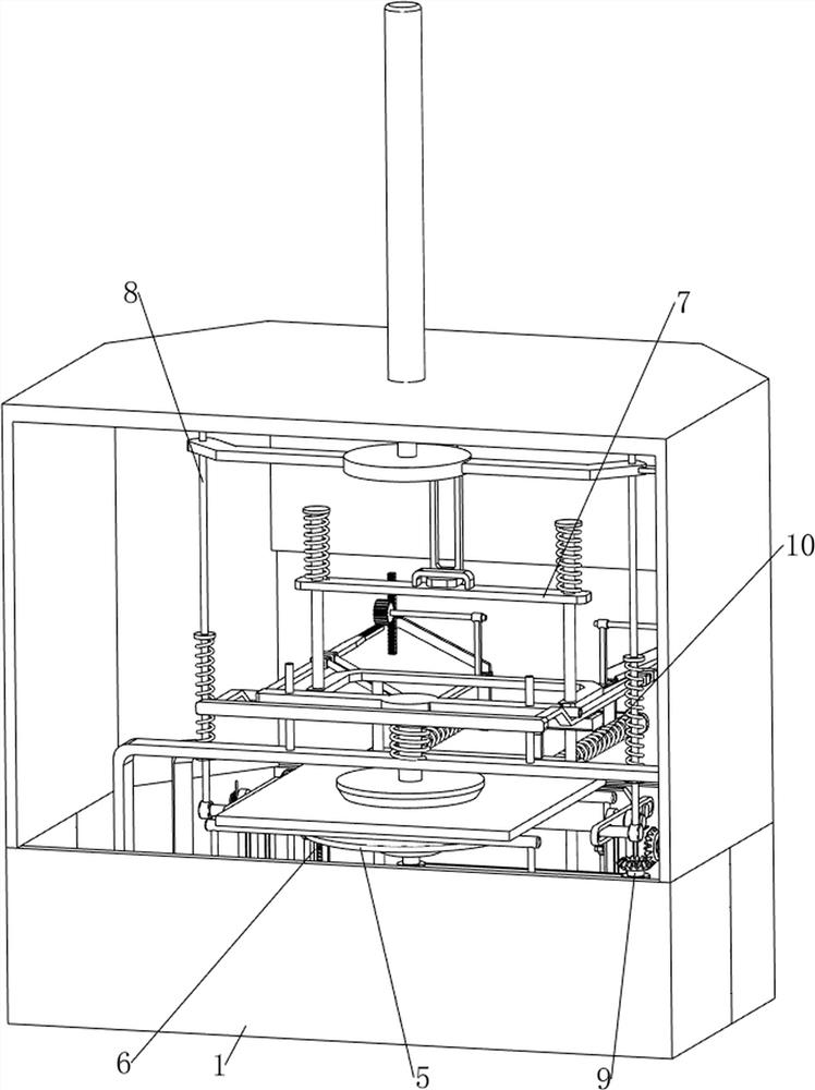
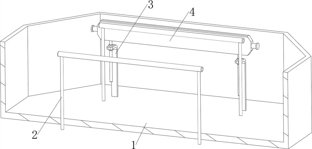
[0030] A steel plate bending vertical numerical control machine tool, such as Figure 1-Figure 4 As shown, it includes a frame body 1, a fixing frame 2, a first support plate 3, a bending plate 4, a clamping mechanism 5 and a locking mechanism 6, and the frame body 1 is connected with a fixing frame 2 on both sides at the front and back, and the frame body 1 The first support plate 3 is connected to the rear of the left and right sides of the interior, and the bending plate 4 is slidably connected between the first support plates 3 on both sides. The inner bottom of the frame body 1 is connected to the clamping mechanism 5 in the middle. 1. The locking mechanism 6 is connected to the left side of the inner bottom.
[0031] The clamping mechanism 5 includes a turntable 50, a second support plate 51, a pressure plate 52, a first spring 53 and a slide plate 54. The turntable 50 is rotatably connected in the middle of the inner bottom of the frame body 1, and the second support is...
Embodiment 2
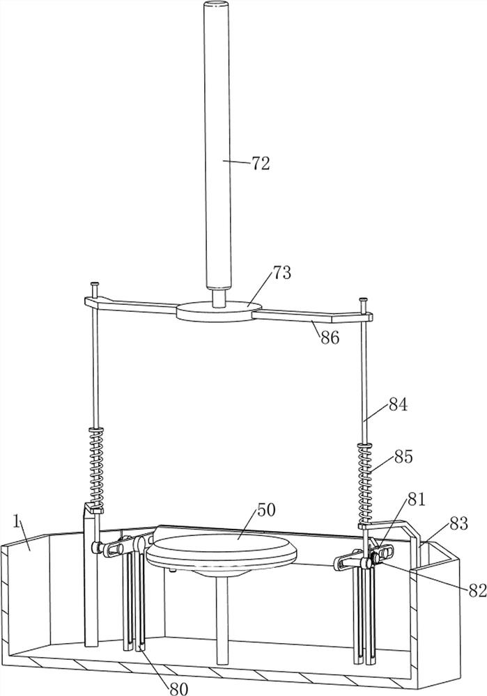
[0035] On the basis of Example 1, such as figure 1 and Figure 5 Shown, also include hold-down mechanism 7, hold-down mechanism 7 includes first support frame 70, lower pressing plate 71, cylinder 72, fixed ring 73, fixed plate 74, movable plate 75, the 3rd spring 76, frame body 1 A first support frame 70 is connected to the rear of the inner bottom, and a lower pressure plate 71 is slidably connected to the upper front of the left and right sides of the first support frame 70. The upper middle part of the frame body 1 is connected to a cylinder 72, and the lower end of the telescopic rod of the cylinder 72 is connected to a fixed Ring 73, fixed ring 73 rear side middle part is connected with fixed plate 74, is connected with movable plate 75 slidingly between the left and right sides of lower pressing plate 71 top, movable plate 75 cooperates with fixed plate 74, lower pressing plate 71 left and right sides tops and movable A third spring 76 is sleeved between the left and r...
Embodiment 3
[0038] On the basis of Example 2, such as figure 1 and Figure 6 As shown, a bending mechanism 8 is also included, and the bending mechanism 8 includes a third support plate 80, a rotating plate 81, a torsion spring 82, a support rod 83, a pressing column 84, a fourth spring 85 and a fixed rod 86, and the frame The rear of the left and right sides of the bottom of the body 1 is connected with a third support plate 80, the upper part of the third support plate 80 on both sides is provided with a rotating plate 81, and the upper part of the third support plate 80 on both sides is connected with a torsion spring 82 The other ends of the torsion springs 82 on both sides are connected to the rotating plates 81 on both sides, and the rear of the left and right sides of the bottom of the frame body 1 is connected with support rods 83, and the support rods 83 on both sides are provided with lower parts in the middle of the front and upper sides. Pressing post 84, pressing down post 8...
PUM
 Abstract
Description
Claims
Application Information
 - R&D Engineer
- R&D Manager
- IP Professional
- Industry Leading Data Capabilities
- Powerful AI technology
- Patent DNA Extraction
Browse by: Latest US Patents, China's latest patents, Technical Efficacy Thesaurus, Application Domain, Technology Topic, Popular Technical Reports.
© 2024 PatSnap. All rights reserved.Legal|Privacy policy|Modern Slavery Act Transparency Statement|Sitemap|About US| Contact US: help@patsnap.com