
Technological method for offshore platform shipborne circulating well washing and return liquid purification treatment

An offshore platform, purification and treatment technology, applied in the direction of flushing wellbore, earthwork drilling, wellbore/well components, etc. It is easy to pollute a large area, it is beneficial to navigation safety, and the effect of reducing the amount of sewage

Inactive Publication Date: 2022-02-08
胜利油田畅海石油技术有限公司 +1
View PDF6 Cites 0 Cited by
  • Summary
  • Abstract
  • Description
  • Claims
  • Application Information

AI Technical Summary

Problems solved by technology

[0004] In the past, the well-washing process of ship-borne equipment was relatively simple. Referring to the well-washing mode of water injection wells in land oilfields, a simple process of clean water tank-pump skid-water injection well-sewage liquid tank was adopted. The existing problem is that the well-washing fluid cannot be circulated The amount of waste liquid produced is huge; the well control measures are not perfect, and cannot adapt to the actual situation of changing offshore weather and inconvenient transportation, so the efficiency of well cleaning is low and the cost of well cleaning is high.

Method used


Image

  • Technological method for offshore platform shipborne circulating well washing and return liquid purification treatment
  • Technological method for offshore platform shipborne circulating well washing and return liquid purification treatment
  • Technological method for offshore platform shipborne circulating well washing and return liquid purification treatment

Examples


Embodiment 1

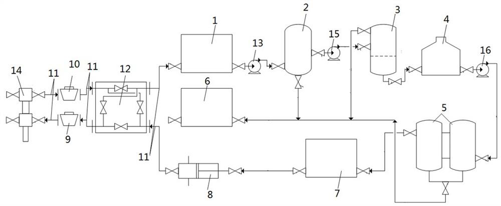
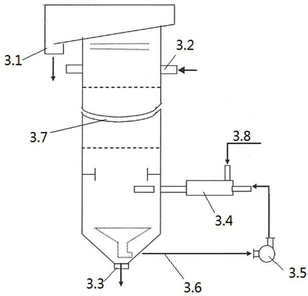
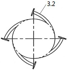
[0035] Embodiment 1, with reference to Figure 1-4 , a ship-borne circulating well flushing and liquid return treatment device for offshore platform water injection wells mentioned in the present invention, including a special well flushing ship, a camera is installed on the special well flushing ship, and a first-level buffer is also arranged on the special well flushing ship Tank 1, settling tank 2, oil-water separator 3, secondary buffer tank 4, fine filter 5, sewage tank 6, clean water tank 7, marine well washing pump skid 8, first outlet cock valve 9, second outlet cock Valve 10, high-pressure hose 11, front and back washing skid 12, first lift pump 13, second lift pump 15 and third lift pump 16;

[0036] The outlet on the upper side of the Christmas tree 14 is connected to the inlet of the front and back washing skid 12 through the high-pressure rubber hose 11, the outlet of the front and back washing skid 12 is connected to the inlet of the first-stage buffer tank 1 thr...

Embodiment 2

[0050] Embodiment 2: refer to Figure 5 , the present invention refers to a process method for circulating well flushing and return liquid on board a water injection well on an offshore platform. During the well flushing process, a turbidimeter is used to measure that the return liquid is oily sewage without particulate matter, and the equipment and connecting pipelines can be readjusted. .

[0051] Compared with Embodiment 1, the difference is that the secondary buffer tank 4 and the fine filter 5 are not connected.

[0052] The specific working process is as follows:

[0053] Step 1: The return fluid from well flushing enters the first-stage buffer tank 1 through the high-pressure rubber hose 11 through the second outlet cock 10 and the positive and negative flushing skid 12. After entering the settling tank 2, relatively large impurities are deposited at the bottom of the settling tank 2. The high-pressure well flushing fluid of the injection well is pressurized by the se...

Embodiment 3

[0056] Embodiment 3, with reference to Image 6 , the present invention refers to a process method for circulating well washing and return liquid purification treatment on board the offshore platform. During the well washing process, a turbidity meter is used to measure that the return liquid is muddy or sedimentary sewage. When it does not contain oil, it can be re- Adjust equipment.

[0057] Compared with Example 1, the difference is that the oil-water separator 3 and the secondary buffer tank 4 are omitted.

[0058] When using it specifically:

[0059]The flushing liquid returns to the primary buffer tank 1 through the high-pressure hose 11 through the second outlet plug valve 10 and the positive and negative washing skid 12. After decompression and pre-sedimentation, the first lift pump 13 is turned on and enters the settling tank through the pipeline. 2. Larger impurities are deposited at the bottom of the settling tank 2, and the liquid returned from well washing is pr...


PUM


Abstract

The invention relates to the technical field of offshore oilfield water injection well washing, and in particular relates to a technological method for offshore platform shipborne circulating well washing and return liquid purification treatment. According to the technical scheme, an outlet in the upper side of a Christmas tree is connected with an inlet of a forward and reverse washing skid through a high-pressure rubber pipe, an outlet of the Christmas tree is connected with a first-stage buffer tank, the first-stage buffer tank is connected with a settling tank through a first lifting pump, the settling tank is connected to an oil-water separator, a water outlet of the oil-water separator is connected with a second-stage buffer tank, an outlet of the second-stage buffer tank is connected to a fine filter, a lower-end outlet of the fine filter is connected to a dirty liquid tank, an upper-side outlet of the fine filter is connected to a clear water tank, the clear water tank is connected to a marine well washing pump skid, an outlet of the marine well washing pump skid is connected to the forward and reverse washing skid, and the forward and reverse washing skid is connected to a lower-side circulating inlet of the Christmas tree through a first outlet plug valve. The method has the beneficial effects that the amount of dirty liquid generated by well washing of an offshore water injection well is reduced, the production efficiency is improved, the construction safety is improved, and the environmental protection effect is improved.

Description

technical field [0001] The invention relates to the technical field of well flushing of water injection wells in offshore oil fields, in particular to a process method for circulating well flushing and return liquid purification treatment on board an offshore platform. Background technique [0002] At present, the flushing of water injection wells is an effective means of water injection maintenance in oilfields, and it is also a very important daily work. The existing water injection well flushing process needs to pump clean water into the wellbore through the plunger pump, and replace the original water in the wellbore to the ground, so as to achieve the purpose of cleaning the wellbore. The well flushing process requires a large amount of water resources. At the same time, the returned well flushing fluid contains impurities such as crude oil and sediment, which is easy to pollute the environment and waste a lot of water resources, and there is a certain risk of well cont...

Claims


Application Information

Patent Timeline
Patent Type & Authority Applications(China)
IPC IPC(8): E21B21/00E21B21/06
CPCE21B21/001E21B21/06E21B21/066E21B21/063
Inventor 唐丽丽王磊张立亭王辉
Owner 胜利油田畅海石油技术有限公司
Learn More