Integrated device for automobile fuel steam desorption

A fuel vapor, integrated device technology, which is applied to the charging system, adding non-fuel substances to fuel, engine components, etc. The effect of saving production costs and convenient production and processing

Pending Publication Date: 2022-02-08
HEBEI CHINAUST AUTOMOTIVE PLASTICS CORP LTD
View PDF0 Cites 0 Cited by
  • Summary
  • Abstract
  • Description
  • Claims
  • Application Information

AI Technical Summary

Problems solved by technology

However, the setting of two pipelines will result in the defects of a large number of parts and a large space occupation, which will virtually increase the production cost and needs to be improved.

Method used


Image

  • Integrated device for automobile fuel steam desorption
  • Integrated device for automobile fuel steam desorption
  • Integrated device for automobile fuel steam desorption

Examples


Embodiment 1

[0049] Embodiment 1: The embodiment of this application discloses an integrated device for desorption of automobile fuel vapor.

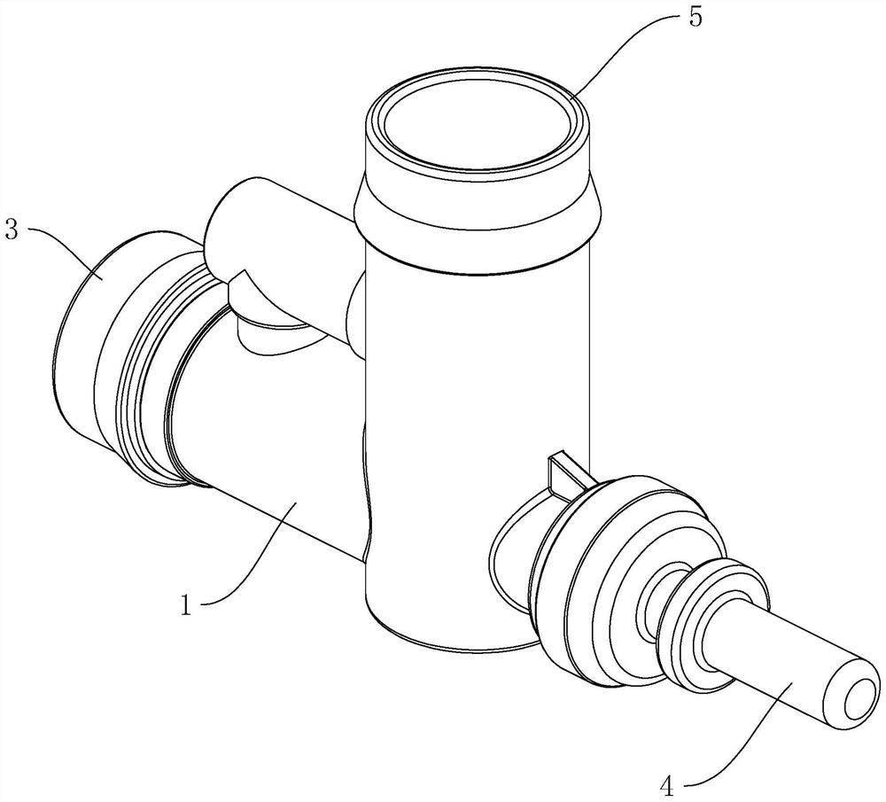
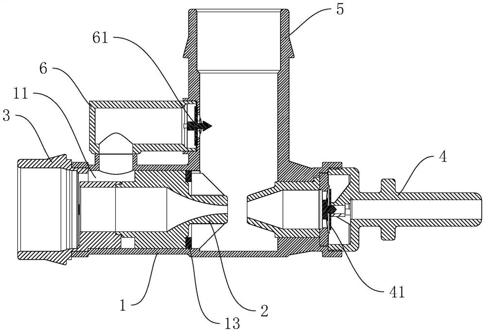
[0050] refer to figure 1 , figure 2 , the integrated device includes a Venturi tube 1 , a Venturi structure 2 , an installation end 3 , an installation through pipe 4 and an installation end pipe 5 .

[0051] refer to figure 1 , figure 2 The venturi tube 1 is arranged horizontally, and the installation end pipe 5 is vertically connected to the top of the venturi tube 1, and forms a tee pipe with the venturi tube 1, and is used to communicate with the carbon tank of the car at the same time. Wherein the installation end 3 and the installation through pipe 4 are respectively arranged at the two ends of the venturi tube 1, and are used to communicate with the position between the intake manifold and the throttle valve and the automobile air filter respectively. And the installation end 3 is a quick connector, and the installation through pipe 4 i...

Embodiment 2

[0073] Embodiment 2: The embodiment of this application discloses an integrated device for desorption of automobile fuel vapor.

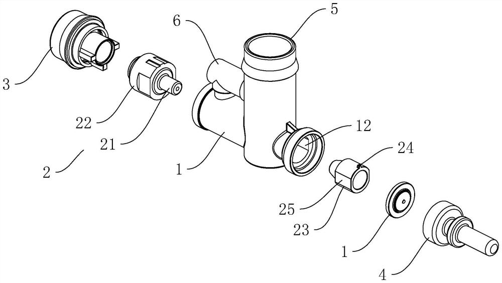
[0074] refer to Figure 5 , the difference from Embodiment 1 is that the shrink tube 21 includes a main pipe 216 and a connecting block 217 . One end of the main pipe 216 is connected to the installation head 3 , and the other end extends into the venturi 1 , and the collar 22 and the guide plane 25 are integrally formed on the outer wall of the main pipe 216 .

[0075] refer to Figure 5 , wherein at least one connection block 217 is provided and arranged at intervals. The connection block 217 is arranged between the outer wall of the main pipe 216 and the inner wall of the installation terminal 3 . Wherein the installation end 3, the main pipe 216 and the connection block 217 are integrally formed to realize one-time injection molding of the installation end 3, the main pipe 216 and the connection block 217, which is convenient for production a...


PUM


Abstract

The invention relates to an integrated device for automobile fuel steam desorption. The integrated device comprises a venturi tube, a venturi structure, a mounting end, a mounting through tube, a positive pressure valve plate, a mounting end tube, a branch and a negative pressure valve plate. The venturi structure is positioned in the venturi tube, and the mounting end, the mounting through tube and the mounting end tube are communicated with the venturi tube to form a tee joint; one end of the branch is connected with the mounting end tube, the other end of the branch is connected with the venturi tube, and a cavity is formed in one end of the venturi tube and one end of the venturi structure and is communicated with the mounting end and the branch, wherein the positive pressure valve plate is arranged in the mounting through tube, and the negative pressure valve plate is arranged in the branch. By arranging the integrated device integrating positive pressure desorption and negative pressure desorption, free switching between the positive pressure desorption and the negative pressure desorption of fuel steam is achieved, and the number of parts and the occupied space are reduced. And meanwhile, the nested and detachable venturi structures are arranged, so that the combined installation and free replacement of the venturi structures are realized, and the production, processing, maintenance and replacement processes are more convenient.

Description

technical field [0001] The present application relates to the field of fuel vapor desorption, in particular to an integrated device for desorption of automobile fuel vapor. Background technique [0002] The amount of volatilization allowed by the car into the atmosphere needs to be strictly controlled. In the car fuel evaporation control system, the fuel vapor from the fuel tank is often temporarily stored in the carbon tank connected to it, and finally desorbed into the engine for combustion. At present, the technology of arranging venturi tubes and matching check valves in the fuel evaporation control system is considered to be an effective means to improve the desorption efficiency of fuel vapor in the carbon canister. [0003] Currently, fuel vapor desorption routes include negative pressure desorption route and positive pressure desorption route. The negative pressure desorption route is for the automobile turbocharger to start working and inhale air inwardly, and the ...

Claims


Application Information

Patent Timeline
Patent Type & Authority Applications(China)
IPC IPC(8): F02M25/08F04F5/16F04F5/44F04F5/46
CPCF02M25/0854F02M25/0872F04F5/16F04F5/46F04F5/44
Inventor 马宝玲夏雷鸣左文杰李立涛王玮丰
Owner HEBEI CHINAUST AUTOMOTIVE PLASTICS CORP LTD
Why Eureka
Try Eureka