Electronic shade, LED lamp bead, light source system and light-emitting equipment

A technology of light source system and LED chip, which is applied in the field of light source system and lighting equipment, electronic mask, and LED lamp beads, can solve the problems of waste of resources, poor user experience, waste of raw materials, etc., achieve good lighting effect, improve and The effect of improving user experience and convenience

Pending Publication Date: 2022-02-08
XUNTENG (GUANGDONG) TECH CO LTD
View PDF0 Cites 1 Cited by
  • Summary
  • Abstract
  • Description
  • Claims
  • Application Information

AI Technical Summary

Problems solved by technology

[0002] At present, lighting devices either only have a search function or a uniform light function, and cannot be switched and controlled, and it is impossible to achieve a variety of uniformity controls between the search function and the uniform light function.
For example, searchlights, spotlights, flashlights, street lights, fishing lights, emergency lights, fire emergency lights, mobile phone fill lights, etc. only have searchlight functions, but cannot dynamically switch to uniform light functions; for example, desk lamps, reading lights, floor lamps, Shooting fill light, live broadcast fill light, camera fill light, face recognition device fill light, etc. only have the function of uniform light, but cannot switch to the search light function
[0003] Although the multi-functional flashlight has both the searchlight function and the uniform light function, but the two functions belong to two independent lighting systems, a large number of lamp beads are required to realize the searchlight and uniform light functions, resulting in waste of raw materials and more waste of resources and environmental pollution
[0004] Due to the single function of the current lighting system, it is impossible to provide different lighting effects according to different application scenarios and different environments, resulting in poor user experience

Method used


Image

  • Electronic shade, LED lamp bead, light source system and light-emitting equipment
  • Electronic shade, LED lamp bead, light source system and light-emitting equipment
  • Electronic shade, LED lamp bead, light source system and light-emitting equipment

Examples


Embodiment 1

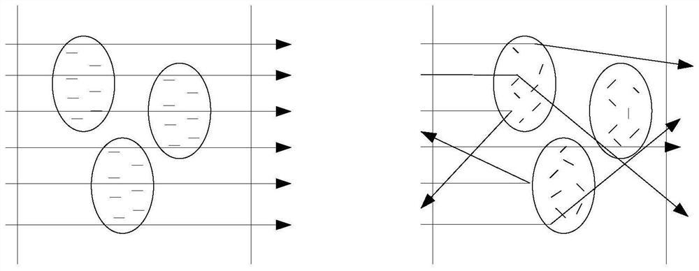
[0050] Such as figure 2 as shown, figure 2It is a schematic diagram of the working principle of the electroluminescent liquid crystal atomization film. Electro-induced liquid crystal atomized film is also called electro-induced liquid crystal atomized glass, electrically controlled atomized film, electrically controlled atomized glass, energized atomized film, energized atomized glass, etc. A mixture of liquid polymers, which is then cured, forms a sandwich structure, so it can be in glass or film form. According to the characteristics of liquid crystal deflection in the electric field, the control of the light passing state of the glass can be realized through the electro-induced liquid crystal atomization film. figure 2 It is a schematic diagram of the optical path comparison between the on state and the off state of the electroluminescent liquid crystal atomization film. The left side is the schematic diagram of the optical path in the open state (power-on working sta...

Embodiment 2

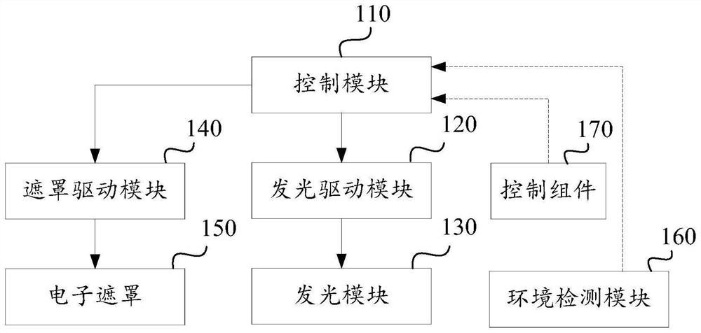
[0061] Please refer to figure 1 with Figure 4 , figure 1 A schematic structural diagram of a light source system provided in this embodiment, Figure 4 It is a schematic diagram of the illumination structure of the light source system.

[0062] Such as figure 1 As shown, the light source system in this embodiment includes the electronic mask 150 mentioned in the previous embodiment, and also includes a control module 110, a light-emitting driving module 120, a light-emitting module 130 and a mask driving module 140;

[0063] The first control terminal of the control module 110 is connected to the control input terminal of the light-emitting drive module 120 for controlling the light-emitting drive module 120; the second control terminal of the control module 110 is connected to the mask The control input terminals of the driving module 140 are connected to control the mask driving module 140;

[0064] The output terminal of the light-emitting driving module 120 is connec...

Embodiment 3

[0076] A light source system provided by an embodiment of the present invention is suitable for simultaneous configuration of a control component and an environment detection module, and the control module can be regarded as including a manual mode and / or an automatic mode.

[0077] Such as figure 1 As shown, the control component 170 can be a power switch, which can be regarded as a manual mode at this time. When the user manually switches the power switch, the control module 110 detects a corresponding control signal, and the mask driving module 140 enters a power-on or power-off state, causing the electronic The mask 150 enters the closed state or the open state, so as to realize the uniformity control of the light, control the scattering state of the light emitted by the light emitting module 130, and realize the switching between the search light mode and the uniform light mode.

[0078] The control component 170 can also be an electronic circuit with a selection button o...


PUM

PropertyMeasurementUnit
transparencyaaaaaaaaaa

Abstract

The embodiment of the invention discloses an electronic shade, an LED lamp bead, a light source system and light-emitting equipment. The scheme is suitable for equipment and devices comprising LED lamp beads, a lampshade, a photographing light supplementing lamp, a mobile phone light supplementing lamp, a camera light supplementing lamp, a face recognition equipment light supplementing lamp, a spotlight, a flashlight, a fishing lamp, a pendant lamp, a ceiling lamp, a desk lamp, a reading lamp, a floor lamp, a searchlight, an outdoor illuminating lamp, a street lamp, an emergency lamp, a fire emergency lamp, an automobile lamp, a traffic lamp, a lamp belt, a lamp strip, a lamp panel, advertising characters, signboard lamp box and having lighting function, can provide various lighting effects with different light scattering degrees, achieves better lighting effects in different application scenes and different environments, improves the convenience of equipment, and greatly improves the user experience and the use experience.

Description

technical field [0001] The embodiments of the present application relate to the field of light source control, and in particular, to an electronic shade, an LED lamp bead, a light source system, and a light emitting device. Background technique [0002] At present, the lighting device either only has the search function or the uniform light function, and cannot be switched and controlled, let alone realize various uniformity control between the search function and the uniform light function. For example, searchlights, spotlights, flashlights, street lights, fishing lights, emergency lights, fire emergency lights, mobile phone fill lights, etc. only have searchlight functions, but cannot dynamically switch to uniform light functions; for example, desk lamps, reading lights, floor lamps, Shooting fill light, live broadcast fill light, camera fill light, face recognition device fill light, etc. only have the function of uniform light, but cannot switch to the search light funct...

Claims


Application Information

Patent Timeline
Patent Type & Authority Applications(China)
IPC IPC(8): F21K9/20F21K9/238F21V1/08F21V14/00F21V23/00H05B45/30H05B47/105H05B47/11F21Y115/10
CPCF21K9/20F21K9/238F21V1/08F21V14/003F21V23/003H05B45/30H05B47/105H05B47/11F21Y2115/10Y02B20/40
Inventor 简伟明皮爱平黄飞鹰梁华贵陈吉宏黄伟涛郑则润孟青陈秋榕皮燕
Owner XUNTENG (GUANGDONG) TECH CO LTD
Why Eureka
Try Eureka