Filter tip rod feeding clamp

A filter rod and material clip technology is applied in the field of filter rod feeding fixtures, which can solve the problems of high labor intensity, affect production quality, increase the failure rate of unloaders, etc., and achieve the effect of realizing full-process automation.

Pending Publication Date: 2022-02-11
HUBEI CHINA TOBACCO IND
View PDF6 Cites 1 Cited by
  • Summary
  • Abstract
  • Description
  • Claims
  • Application Information

AI Technical Summary

Problems solved by technology

Manual operation has problems such as high labor intensity, and the filter rod is easy to fall or loose, which increases the failure rate of the unloading machine and affects the production quality

Method used


Image

  • Filter tip rod feeding clamp
  • Filter tip rod feeding clamp
  • Filter tip rod feeding clamp

Examples


Embodiment Construction

[0009] The following will clearly and completely describe the technical solutions in the embodiments of the present invention with reference to the accompanying drawings in the embodiments of the present invention. Obviously, the described embodiments are only some, not all, embodiments of the present invention. Based on the embodiments of the present invention, all other embodiments obtained by persons of ordinary skill in the art without creative efforts fall within the protection scope of the present invention.

[0010] It should be noted that, in the case of no conflict, the embodiments of the present invention and the features in the embodiments can be combined with each other.

[0011] The present invention will be further described below in conjunction with the accompanying drawings and specific embodiments, but not as a limitation of the present invention.

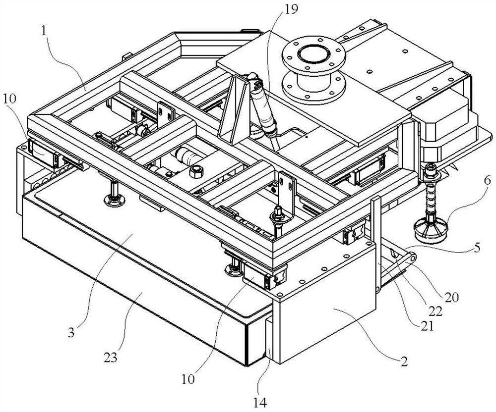
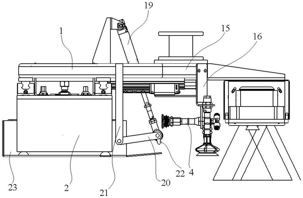
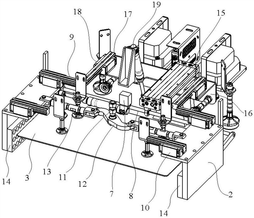
[0012] Such as Figure 1 to Figure 3 As shown, the feeding fixture provided in the embodiment of the present in...


PUM


Abstract

The invention relates to a filter tip rod feeding clamp which comprises a frame, wherein two clamping plates are installed on the frame, the clamping plates are oppositely arranged in a left-right mode, and the clamping plates can move left and right in a reciprocating mode in the direction close to or away from each other; a material blocking plate which is installed on the frame and is located between the clamping plates; an edge opening suction cup which is installed on the frame, wherein the edge opening suction cup can move back and forth in the direction close to/away from the frame in a reciprocating mode; an edge pressing push rod which is mounted on the frame, wherein the edge pressing push rod can move back and forth in the oblique direction of the frame in the direction close to/away from the frame; and a feeding suction cup installed on the frame. A mechanical arm is matched with the clamp, manual operation can be completely replaced, grabbing, clamping and holding and side edge opening treatment of a carton cover with a filter tip rod and grabbing work of an empty carton are achieved, and therefore the full-process automation of a core process is achieved.

Description

technical field [0001] The invention relates to the technical field of mechanical equipment, in particular to a clamp for feeding filter rods. Background technique [0002] When the unloading machine is working, it is necessary to turn the open cartons with filter rods lying flat at 90° first, and then place the cartons into the input port of the unloading machine. At present, this work is mainly done manually . Manual operation has problems such as high labor intensity, and the filter rod is easy to fall or loose, which increases the failure rate of the unloading machine and affects the production quality. Contents of the invention [0003] In view of the above problems, a highly automated filter rod loading jig is now provided. [0004] In the present invention, the use of the mechanical arm to cooperate with the above-mentioned clamp can completely replace the manual operation, and realizes the grabbing, clamping, side opening and edge handling of the carton cover wit...

Claims


Application Information

Patent Timeline
Patent Type & Authority Applications(China)
IPC IPC(8): B65G47/91B65G47/248B65B69/00
CPCB65G47/248B65G47/914B65B69/00
Inventor 易璇孙双郑梦张明玉刘申波乔腾飞阳建军
Owner HUBEI CHINA TOBACCO IND
Why Eureka
Try Eureka