
Consolidation type temporary plugging agent and temporary plugging method

A temporary plugging agent and knotting technology, which is applied in chemical instruments and methods, earth-moving drilling, wellbore/well components, etc. The process is simplified, the temporary plugging effect is good, and the reservoir damage is small.

Pending Publication Date: 2022-02-11
BC P INC CHINA NAT PETROLEUM CORP +1
View PDF6 Cites 1 Cited by
  • Summary
  • Abstract
  • Description
  • Claims
  • Application Information

AI Technical Summary

Problems solved by technology

[0005] The above-mentioned temporary plugging technology is basically based on the friction accumulation (or bridging and enrichment) of temporary plugging particles or fibers in the fracture or the opening (blasthole) to form bridge plugging, but accumulation or enrichment is a fuzzy process, and it is impossible to determine the temporary plugging Timing and location, and also due to the loss of temporary plugging agent, the thickness of temporary plugging formed through accumulation cannot be determined, so the strength and effect of temporary plugging are difficult to guarantee, which affects subsequent fracturing to open new fractures
In addition, the traditional temporary plugging fracturing technology basically determines the amount of temporary plugging agent added according to the change of ground construction pressure, so it is necessary to prepare excessively in advance on the ground, resulting in waste

Method used


Image

  • Consolidation type temporary plugging agent and temporary plugging method
  • Consolidation type temporary plugging agent and temporary plugging method
  • Consolidation type temporary plugging agent and temporary plugging method

Examples


Embodiment 1

[0062] This embodiment provides a consolidated temporary plugging agent that can be used for layered fracturing in low-temperature vertical wells.

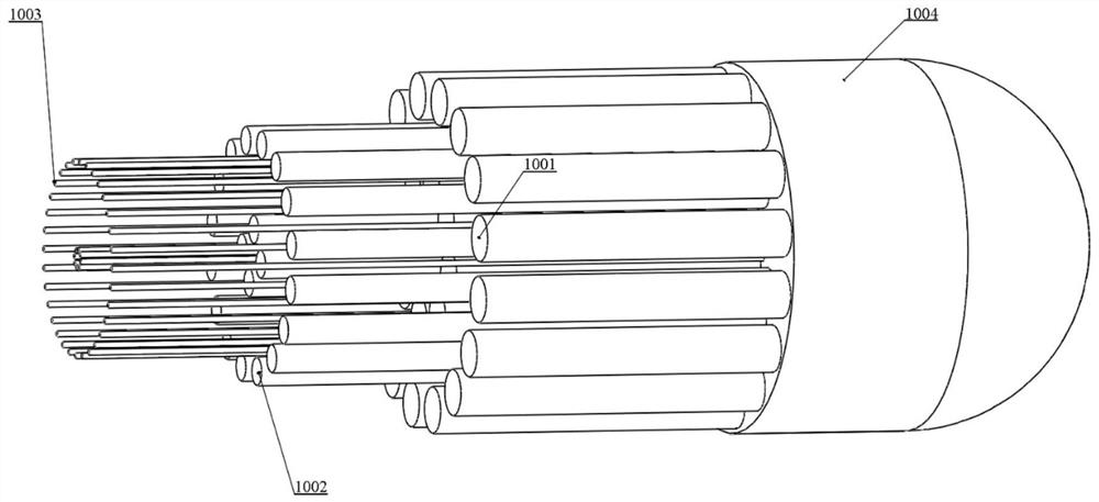
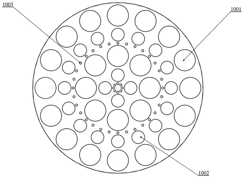
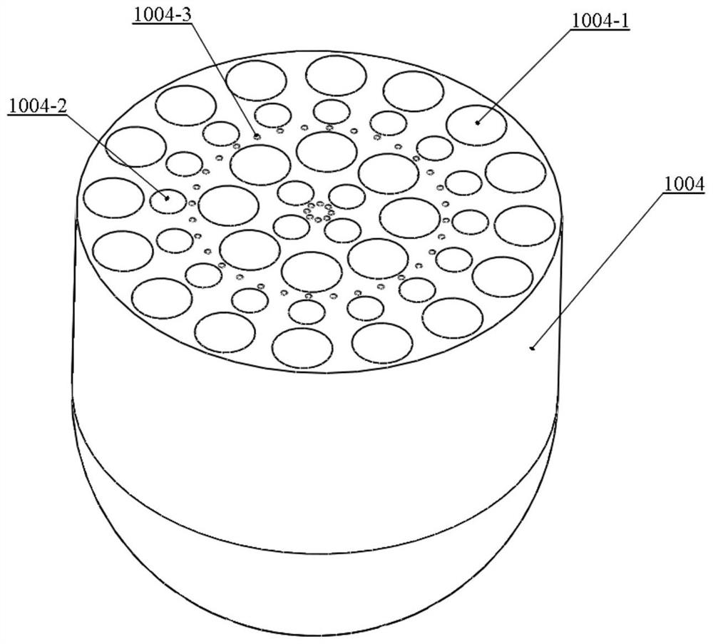
[0063] Such as Figure 1-Figure 4 As shown, the consolidated temporary plugging agent includes a thick wire 1001 , a medium wire 1002 , a thin wire 1003 , a connecting body 1004 and a shell 1005 . The connecting body 1004 includes a thick wire joint 1004-1, a medium wire joint 1004-2 and a thin wire joint 1004-3. The thick wire 1001 is connected to the connecting body 1004 through the thick wire joint 1004-1, the medium wire 1002 is connected to the connecting body 1004 through the medium wire joint 1004-2, and the thin wire 1003 is connected to the connecting body 1004 through the thin wire joint 1004-3. The present invention has no specific limitation on the distribution of thick filaments, medium filaments and thin filaments, as in this embodiment, they can be distributed in circles. The thick wire 1001 of the consolidated te...

Embodiment 2

[0072] This embodiment provides a consolidated temporary plugging agent that can be used for staged fracturing of high-temperature horizontal wells.

[0073] The consolidated temporary plugging agent includes a thick wire 1001, a medium wire 1002, a thin wire 1003, a connecting body 1004 and a shell 1005, wherein the connecting body 1004 includes a thick wire joint 1004-1, a medium wire joint 1004-2 and a thin wire joint 1004 -3. The thick wire 1001 is connected to the connecting body 1004 through the thick wire joint 1004-1, the medium wire 1002 is connected to the connecting body 1004 through the medium wire joint 1004-2, and the thin wire 1003 is connected to the connecting body 1004 through the thin wire joint 1004-3.

[0074] The thick wire 1001 of the consolidated temporary plugging agent has a diameter of 0.5 mm and a length of 30.0 mm, the medium wire 1002 has a diameter of 0.3 mm and a length of 40.0 mm, the thin wire 1003 has a diameter of 0.05 mm and a length of 50....

Embodiment 3

[0083] This embodiment provides a consolidated temporary plugging agent that can be used for temporary plugging in normal temperature vertical well workover.

[0084] The consolidated temporary plugging agent includes a thick wire 1001, a medium wire 1002, a thin wire 1003, a connecting body 1004 and a shell 1005, wherein the connecting body 1004 includes a thick wire joint 1004-1, a medium wire joint 1004-2 and a thin wire joint 1004 -3. The thick wire 1001 is connected to the connecting body 1004 through the thick wire joint 1004-1, the medium wire 1002 is connected to the connecting body 1004 through the medium wire joint 1004-2, and the thin wire 1003 is connected to the connecting body 1004 through the thin wire joint 1004-3.

[0085] The thick filament 1001 of the consolidated temporary plugging agent has a diameter of 0.8mm and a length of 18.0mm, the medium filament 1002 has a diameter of 0.4mm and a length of 24.0mm, the thin filament 1003 has a diameter of 0.1mm and ...


PUM

PropertyMeasurementUnit
diameteraaaaaaaaaa
lengthaaaaaaaaaa
diameteraaaaaaaaaa

Abstract

The invention discloses a consolidation type temporary plugging agent and a temporary plugging method. The consolidation type temporary plugging agent comprises a thick wire, a middle wire, a thin wire and a connecting body; the thick wire, the middle wire and the thin wire are respectively connected with the connecting body to form a whole; and the diameters of the thick wire, the medium wire and the thin wire are sequentially reduced, and the lengths are sequentially increased. The temporary plugging agent is not limited in applicable working conditions and applicable well types. The use amount of the consolidation type temporary plugging agent is small, and the use amount of the consolidation type temporary plugging agent and a plugged hole are basically designed according to a ratio of 1:1. Different numbers, different sizes, different distribution modes and different materials of the thick wires, the middle wires and the thin wires are matched, the thick wires, the middle wires and the thin wires are integrally designed with the connecting body, falling is not prone to occurring, and the temporary plugging effect is better; the technological process is more simplified and is put in one place; self-degradation can be achieved according to needs, and damage to a reservoir is small; and the consolidation type temporary plugging agent can be prefabricated and is convenient to transport.

Description

technical field [0001] The invention relates to the technical field of oil and gas exploitation engineering, in particular to a consolidated temporary plugging agent and a temporary plugging method. Background technique [0002] At present, more than 60% of the new reserves in China are low-permeability and hard-to-produce reserves, and the exploitation of unconventional oil and gas such as shale oil and gas and tight oil and gas is increasingly becoming the main target of various oilfield companies. Fracturing and acidizing reservoir stimulation technologies are the main means to exploit such unconventional oil and gas reservoirs, and staged fracturing and acidizing stimulation technologies are the only way to achieve targeted reservoir stimulation. [0003] Existing technologies for segmental transformation are generally divided into mechanical methods and chemical methods. The commonly used tools in the mechanical method are packers or bridge plugs, which are expensive, ...

Claims


Application Information

Patent Timeline
Patent Type & Authority Applications(China)
IPC IPC(8): C09K8/516E21B33/13
CPCC09K8/516E21B33/13
Inventor 张杨杨向同乔岩刘玉章周福建王永红刘继亮房平亮范应璞侯腾飞李会丽
Owner BC P INC CHINA NAT PETROLEUM CORP
Learn More