Test tool for air compressor and detection method thereof

A technology of air compressors and testing equipment, which is applied in the direction of motor generator testing and measuring device casings, which can solve the problems of inconvenient testing of the output shaft, reduce the ejection of falling objects, and poor use effects, so as to improve the protection effect , increase the effect of use, improve the effect of the scope of application

Pending Publication Date: 2022-02-11
江苏氧滋康电器有限公司
View PDF0 Cites 0 Cited by
  • Summary
  • Abstract
  • Description
  • Claims
  • Application Information

AI Technical Summary

Problems solved by technology

[0004] The purpose of the present invention is to provide a test tool for an air compressor and a detection method thereof, so as to solve the problem of inconvenient adjustment of the position of the motor when the existing motor of the air compressor is detected in the above-mentioned background technology. In the process of testing different types of motors, the positions of the output end shafts of different types of motors are different, which makes it difficult to align the output end shaft with the test end shaft of the dynamometer. The operation is inconvenient, the test is time-consuming, and the use effect is not good. When the connection between the output end and the test end is accidentally damaged and falls off, it is not convenient to reduce the ejection of the falling object to the operator's side, which may cause damage to the operator.

Method used


Image

  • Test tool for air compressor and detection method thereof
  • Test tool for air compressor and detection method thereof
  • Test tool for air compressor and detection method thereof

Examples


Embodiment Construction

[0030] The following will clearly and completely describe the technical solutions in the embodiments of the present invention with reference to the accompanying drawings in the embodiments of the present invention. Obviously, the described embodiments are only some, not all, embodiments of the present invention. Based on the embodiments of the present invention, all other embodiments obtained by persons of ordinary skill in the art without making creative efforts belong to the protection scope of the present invention.

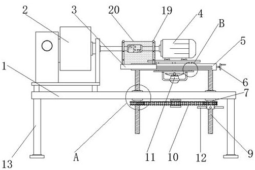
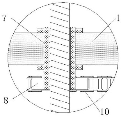
[0031] see Figure 1-Figure 5 , the present invention provides a technical solution: a test tool for an air compressor, including a testing platform 1, a support leg 13 is fixed on the lower surface of the testing platform 1, a dynamometer 2 is arranged on one end of the upper surface of the testing platform 1, and a testing platform 1 The inner side is provided with a rotating ring 7, which is convenient for adjusting the position of the supporting screw rod ...


PUM


Abstract

The invention discloses a test tool for an air compressor and a detection method thereof. The test tool comprises a detection table, wherein supporting legs are fixed to a lower surface of the detection table, a dynamometer is arranged at one end of an upper surface of the detection table, a rotating ring is arranged on the inner side of the detection table, and a supporting screw rod is connected to the inner side of the rotating ring through a first thread part; a first transmission gear is fixed to an outer surface of the rotating ring, a chain is arranged on the outer side of the first transmission gear in a sleeving mode, and a supporting table is fixed to a top end of the supporting screw rod; Through arrangement of the supporting screw rod, the rotating ring, the chain, the first transmission gear, a first adjusting screw rod, an adjusting sliding block and a guiding sliding block, the situation that the position of a motor is inconvenient to adjust, and an output end of the motor and a testing end of the dynamometer are inconvenient to align and connect is avoided, and through arrangement of a fixing plate, a mounting block, a connecting sliding block and a transparent tempered glass plate, an output end of the motor and the testing end of the dynamometer is prevented from being accidentally damaged and falling off, and collision injury to external personnel is avoided.

Description

technical field [0001] The invention belongs to the technical field of compressor testing, and in particular relates to a testing tool for an air compressor and a testing method thereof. Background technique [0002] An air compressor is a device used to compress gas. Air compressors are similar in construction to water pumps. Most air compressors are reciprocating piston, rotary vane or rotary screw. The centrifugal compressor is a very large application. When in use, the motor directly drives the compressor to make the crankshaft rotate, which drives the connecting rod to make the piston reciprocate, causing the cylinder volume to change. Due to the change of the pressure in the cylinder, the air enters the cylinder through the air filter (muffler) through the intake valve. The directional valve (check valve) enters the air storage tank. When the compressor is being processed, in order to facilitate the testing of the motor, it is generally carried out through a dynamom...

Claims


Application Information

Patent Timeline
IPC IPC(8): G01R31/34G01R1/04
CPCG01R31/34G01R1/04
Inventor 赵连群朱明峰李驰驰吴云花
Owner 江苏氧滋康电器有限公司
Why Eureka
Try Eureka