Coupling device for photoelectric conversion and laser radar

A coupling device and photoelectric conversion technology, applied in radio wave measurement systems, instruments, etc., can solve the problems of short distance, optical signal and electrical signal crosstalk, etc., and achieve the effects of reducing crosstalk, isolating optical crosstalk, and reducing losses

Pending Publication Date: 2022-02-11
图达通智能科技(苏州)有限公司
View PDF0 Cites 0 Cited by
  • Summary
  • Abstract
  • Description
  • Claims
  • Application Information

AI Technical Summary

Problems solved by technology

[0003] In the process of signal light transmission, the subunit spacing of the detector array is very close, and stray light exists in the system, which easily causes crosstalk of optical signals and electrical signals between different channels

Method used


Image

  • Coupling device for photoelectric conversion and laser radar
  • Coupling device for photoelectric conversion and laser radar

Examples


Embodiment

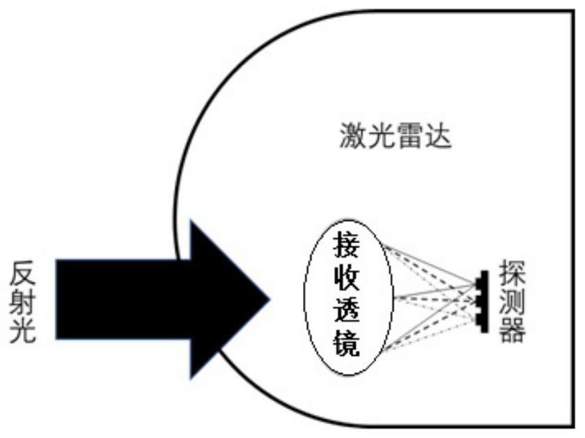
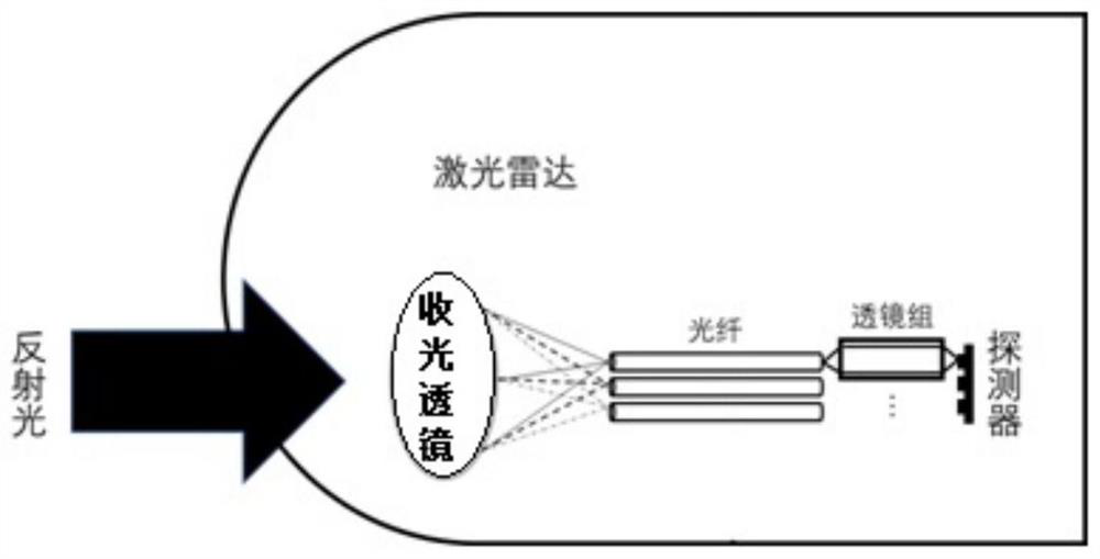
[0020] figure 2 A structural diagram of a coupling device for photoelectric conversion provided by an embodiment of the present invention. In this embodiment, the signal light entering the lidar receiving system is no longer directly converged on the detector after passing through the receiving lens, but the coupled signal light is sent to the detector after being relayed by a corresponding coupling device.

[0021] Specifically, the device includes: a light-receiving lens, a detector, and a coupling device arranged between the light-receiving lens and the detector;

[0022] The coupling device includes an optical fiber and a lens group arranged coaxially, the optical fiber is arranged near the end of the light-receiving lens, and the lens group is arranged near the end of the detector.

[0023] Specifically, the reflected signal light enters the lidar, and is first coupled into the optical fiber array through the light-receiving lens, that is, enters the coupling device. W...


PUM


Abstract

The invention discloses a coupling device for photoelectric conversion and a laser radar. The device comprises a light receiving lens, a detector and a coupling device arranged between the light receiving lens and the detector, the coupling device comprises an optical fiber and a lens group which are coaxially arranged, the optical fiber is arranged close to the light receiving lens end, and the lens group is arranged close to the detector end; the light receiving lens is used for converging signal light reflected by a target reflector and coupling the converged signal light into the optical fiber; the lens group is used for receiving signal light output from the optical fiber; and the detector is used for receiving the signal light passing through the lens group and carrying out photoelectric conversion on the received signal light. The coupling device is arranged between the light receiving lens and the detector of the light receiving system of the laser radar, so that the signal light coupling efficiency of the laser radar is improved, and crosstalk in the signal light transmission process is reduced.

Description

technical field [0001] Embodiments of the present invention relate to the technical field of laser radar, and in particular, to a coupling device for photoelectric conversion and laser radar. Background technique [0002] The optical architecture of lidar mainly includes a transmitting system, a receiving system, and a scanning system. The conventional laser radar emission system is to generate laser light, and the scanning system generates signal light at different angles and emits the whole radar machine. When encountering external objects, reflection occurs, and the signal light returned to the laser radar is collected by the receiving system. The receiving system includes A set of light receiving module, which uses optical lens to focus the signal on the detector and analyzes the signal strength and time information by the subsequent circuit. For details, see figure 1 . [0003] In the process of signal light transmission, the subunit spacing of the detector array is v...

Claims


Application Information

Patent Timeline
Patent Type & Authority Applications(China)
IPC IPC(8): G01S7/481
CPCG01S7/481G01S7/4818G01S7/4816
Inventor 严少诚路丽睿罗思维李宇锋杜奔
Owner 图达通智能科技(苏州)有限公司
Why Eureka
Try Eureka