Supercharge Your Innovation With Domain-Expert AI Agents!

High-speed and high-precision die bonder and use method thereof

A high-precision, crystal-bonding machine technology, applied in the direction of conveyor objects, semiconductor/solid-state device manufacturing, electrical components, etc., can solve the problems of swing arm length accuracy, variation, low efficiency of single dispensing of syringe dispensing valves, etc. , to achieve the effect of improving the precision of solidification, improving efficiency and stability, and shortening the distance of horizontal movement

Pending Publication Date: 2022-02-11
SHANGHAI YINGSHUO ELECTRONICS TECH CO LTD
View PDF0 Cites 3 Cited by
  • Summary
  • Abstract
  • Description
  • Claims
  • Application Information

AI Technical Summary

Problems solved by technology

[0002] The traditional die bonder equipment adopts single swing arm and single suction nozzle for die bonding, and the dispensing method adopts the syringe dispensing valve, which is inefficient for single dispensing, and the traditional mechanism adopts a structure where the wafer and the workbench are placed horizontally. With the development of wafer size, Getting bigger and bigger will lead to the longer and longer the swing arm, and the accuracy will also deteriorate.

Method used


Image

  • High-speed and high-precision die bonder and use method thereof
  • High-speed and high-precision die bonder and use method thereof
  • High-speed and high-precision die bonder and use method thereof

Examples


Embodiment

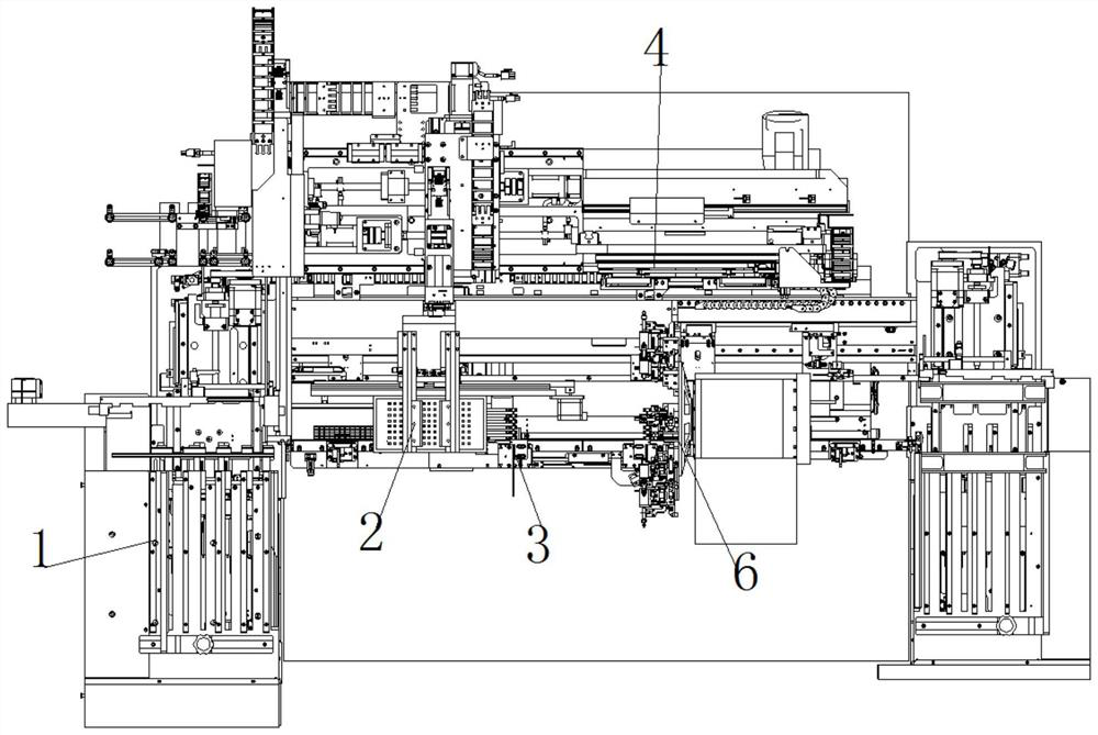
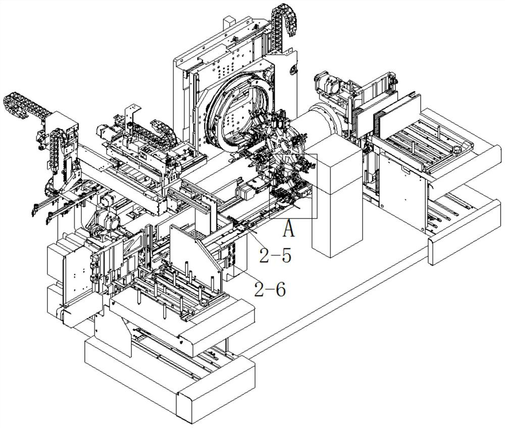
[0051] Embodiment: In this embodiment, eight force control motors 6-5 are arranged at circumferential intervals of the welding head swing arm 6-2. During operation, the crystal frame base 4-1 is first driven to rotate by the wafer rotating motor 4-4 , to correct the angle of the wafer, select the loading mode of the dual-mode loading device 1, when selecting the stacked substrate loading, pull out the loading rail 1-4 from the pushing box mechanism 1-2, and suck the material Mechanism 1-1 moves to the top of stacking table 1-3 to pick up the substrate, and transports the substrate to the feeding track 1-4, and the feeding track 1-4 transports the substrate to the inside of the track. 1-4 is retracted to the bottom of the pusher box mechanism 1-2, the pusher box mechanism 1-2 pushes the material box to be transported to the lifting platform 1-7, and the pusher mechanism 1-6 pushes the substrate from the material box to the inside of the track, Afterwards, the lifting platform 1...


PUM


Abstract

The invention belongs to the technical field of semiconductor die bonding equipment, and particularly relates to a high-speed and high-precision die bonder and a use method thereof.The high-speed and high-precision die bonder comprises a dual-mode feeding device, a feeding track, a glue brushing mechanism, a wafer table, an ejector pin mechanism, a die bonding mechanism and a discharging device; the dual-mode feeding device is arranged at the feeding end of teh feeding track; and the glue brushing mechanism is arranged above the front portion of the feeding track, the wafer table is vertically arranged on one side of the rear portion of the feeding track, the ejector pin mechanism is arranged in the middle of the wafer table, the die bonding mechanism is vertically arranged above the rear portion of the feeding track in a rotating mode, the rotating axis of the die bonding mechanism is parallel to the wafer table, and the discharging device is arranged at the discharging end of the die bonding mechanism. Compared with the prior art, the wafer table is vertically arranged, the rotation axis of the die bonding mechanism is parallel to the wafer table, the welding head does vertical circular motion on one side of the wafer table, the size of a wafer is enlarged, the length of a suction nozzle swing arm is not affected, the die bonding precision is improved, a steel mesh printing mode is adopted as a dispensing mode, and the efficiency and the stability are improved.

Description

technical field [0001] The invention belongs to the technical field of semiconductor crystal-bonding equipment, in particular to a high-speed and high-precision crystal-bonding machine and a method for using the same. Background technique [0002] The traditional die bonder equipment adopts single swing arm and single suction nozzle for die bonding, and the dispensing method adopts the syringe dispensing valve, which is inefficient for single dispensing, and the traditional mechanism adopts a structure where the wafer and the workbench are placed horizontally. With the development of wafer size, Getting bigger and bigger will cause the swing arm to be longer and longer, and the accuracy will also deteriorate. [0003] With the rapid development of the semiconductor industry, the market has higher and higher requirements for the speed, precision and reliability of die-bonding equipment, and there is an urgent need to improve equipment performance. [0004] Therefore, it is n...

Claims


Application Information

Patent Timeline
IPC IPC(8): H01L21/683H01L21/48H01L21/677
CPCH01L21/6838H01L21/6773H01L21/4814
Inventor 渠敬国彭清龙王世源
Owner SHANGHAI YINGSHUO ELECTRONICS TECH CO LTD
Features
  • R&D
  • Intellectual Property
  • Life Sciences
  • Materials
  • Tech Scout
  • Unparalleled Data Quality
  • Higher Quality Content
  • 60% Fewer Hallucinations
Learn More