
Airflow duct structure of hot plate

A hot plate and airflow technology, applied to electrical components, devices for coating liquid on the surface, coatings, etc., can solve problems such as hot plate exhaust, and achieve the effect of improving exhaust efficiency

Pending Publication Date: 2022-02-15
宁波润华全芯微电子设备有限公司
View PDF4 Cites 0 Cited by
  • Summary
  • Abstract
  • Description
  • Claims
  • Application Information

AI Technical Summary

Problems solved by technology

[0004] Therefore, the embodiment of the present invention provides an air flow channel structure for a hot plate, which effectively solves the problem of how to exhaust the hot plate for baking in a heating chamber that can accommodate multiple hot plates.

Method used


Image

  • Airflow duct structure of hot plate
  • Airflow duct structure of hot plate
  • Airflow duct structure of hot plate

Examples


Embodiment Construction

[0041] The following will clearly and completely describe the technical solutions in the embodiments of the present invention with reference to the accompanying drawings in the embodiments of the present invention. Obviously, the described embodiments are only some, not all, embodiments of the present invention. Based on the embodiments of the present invention, all other embodiments obtained by persons of ordinary skill in the art without creative efforts fall within the protection scope of the present invention.

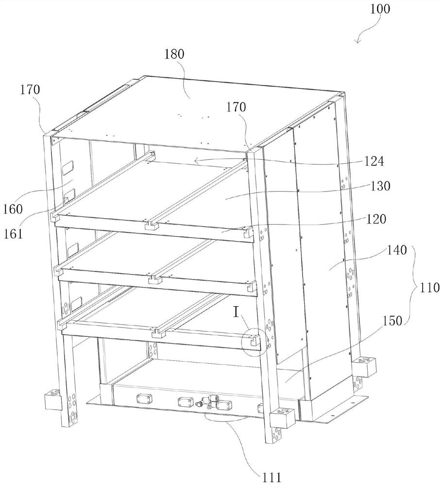
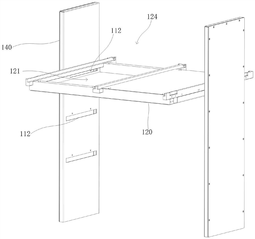
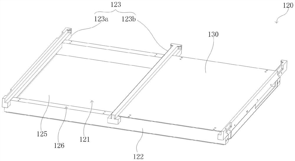
[0042] see Figure 1-2 , which provides an air flow channel structure 100 for a hot plate according to an embodiment of the present invention. The air flow channel structure 100 includes, for example: an exhaust duct 110 , an air guide unit 120 and a sealing plate 130 . Among them, the exhaust duct 110 is provided with an exhaust port 111 and an air guide port 112. The exhaust duct 110 is used to collect the exhaust gas generated when the hot plate bakes the wafer,...


PUM


Abstract

The invention discloses an airflow duct structure of a hot plate. The airflow duct structure comprises: an exhaust duct provided with an exhaust outlet and an air guide port; an air guide unit which is communicated with the air guide port, wherein the air guide unit is provided with a plurality of hot plate mounting ports; and a sealing plate which is detachably connected with the hot plate mounting ports, wherein the hot plate mounting ports are sealed through the sealing plate when not used; and when the hot plate mounting ports are used, the hot plate mounting ports are connected with the hot plate, and the hot plate installation opening is used for discharging waste gas generated when the hot plate heats a wafer. According to the airflow duct structure, the problem of how to control the conduction of any number of hot plates and the exhaust pipeline in the heating cavity capable of accommodating a plurality of hot plates is effectively solved.

Description

technical field [0001] The invention relates to the field of wafers in the semiconductor industry, in particular to an airflow duct structure of a hot plate. Background technique [0002] Coating and developing machine is used for photoresist coating, baking, development, cleaning of the lower surface of the wafer, and rinsing of the wafer surface with deionized water, etc. During the baking process of the wafer, the wafer needs to be placed on the hot plate, and the hot plate is placed in the heating chamber to evaporate the photoresist and moisture, and the gas generated by the baking is discharged through the air flow channel structure. [0003] At present, in order to improve the efficiency of wafer baking, multiple hot plates can be placed in the same heating chamber, and each hot plate corresponds to a wafer. Compared with each hot plate in a separate heating chamber, this method has higher space utilization, so that the maximum efficiency of wafer baking can be obtai...

Claims


Application Information

Patent Timeline
IPC IPC(8): B05D3/02H01L21/67
CPCB05D3/0254H01L21/67109H01L21/67248H01L21/67103
Inventor 汪钢傅立超
Owner 宁波润华全芯微电子设备有限公司
Learn More