
A valve locking mechanism and its switchgear

A technology of locking mechanism and valve, which is applied in the direction of pull-out switchgear, switchgear, switchgear components, etc., can solve the problems of shaking and bumping the valve, the moving contact of the handcart bumping into the valve, and the injury of the operator, etc., to achieve Reduce the requirements for the movement accuracy of the handcart, overcome the easy jamming, and smooth up and down movement

Active Publication Date: 2022-04-05
江苏国控电力设备有限公司
View PDF6 Cites 0 Cited by
  • Summary
  • Abstract
  • Description
  • Claims
  • Application Information

AI Technical Summary

Problems solved by technology

[0003] Publication No. CN204577956U provides a valve mechanism for a high-voltage electric cabinet. By pressing the main connecting rod, it drives the second connecting rod and the fourth connecting rod to move, so that the upper valve and the lower valve are opened, although the valve can be locked. , but there are still the following deficiencies, 1. The direction of movement of the upper valve and the lower valve is only guided by the upper guide rod and the lower guide rod, so that the friction force is relatively large when moving like this, and it is easier to get stuck and the upper valve and the lower valve After closing, only the connecting rod is connected with it, and it is easy to shake up and down and bump up and down during transportation or hoisting, which may easily cause damage to the valve; 2. When pushing the upper valve and the lower valve to move, it is necessary to press the main connecting rod accurately. To push, the structure on the handcart needs to be closely attached to the main connecting rod. The movement accuracy of the handcart is high. Once the movement of the handcart has a certain deviation, it is easy to cause the moving contact of the handcart to directly hit it. The valve is damaged; 3. There is no inspection port on the valve. When installing and fixing the static contacts and screw rods inside the contact box, the valve needs to be opened before installation. At this time, the handcart cannot be installed, and it needs to be opened manually. For the valve, it is not only cumbersome to manually press the main link, but also if the pressure is not in place, the valve will be reset directly, which is easy to cause damage to the operator

Method used


Image

  • A valve locking mechanism and its switchgear
  • A valve locking mechanism and its switchgear
  • A valve locking mechanism and its switchgear

Examples


Embodiment

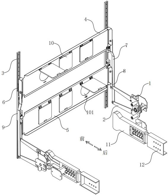
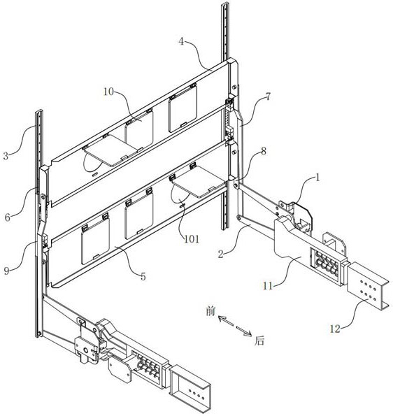
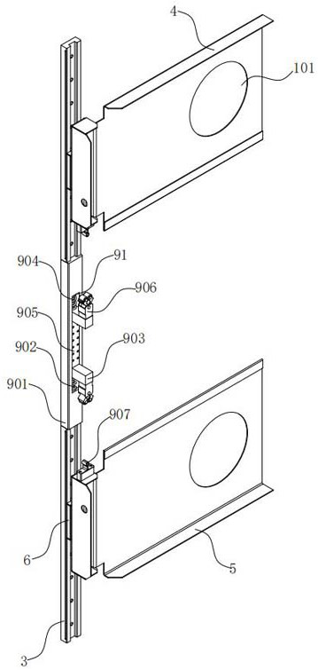
[0033] see Figure 1 to Figure 9 , the present invention provides a technical solution:

[0034]A valve locking mechanism, including a mounting frame 1, a crank mechanism 2, a sliding groove 3, an upper valve 4, a lower valve 5, a sliding block 6, an upper connecting rod 7, a lower connecting rod 8, a buffer fixing mechanism 9, and an inspection door 10 , pushing mechanism 11 and impact frame 12, wherein:

[0035] The sliding groove 3 and the buffer fixing mechanism 9 are installed on the contact box partition 13 of the handcart room of the switch cabinet, the sliding groove 3 is arranged on the upper and lower ends of the buffer fixing mechanism 9, and the upper valve 4 and the lower valve 5, a sliding block 6 is fixed on the side, and the sliding block 6 connected to the upper valve 4 and the lower valve 5 is respectively stuck in the sliding groove 3 at the upper and lower ends of the buffer fixing mechanism 9, and the sliding block 6 can slide up and down in the sliding g...


PUM


Abstract

The invention provides a valve locking mechanism and its switchgear, including a mounting frame, a lever arm mechanism, a sliding groove, an upper valve, a lower valve, a sliding block, an upper connecting rod, a lower connecting rod, a buffer fixing mechanism, an inspection door, and a pushing mechanism And the impact frame, the up and down movement of the upper valve and the lower valve of the present invention is guided by the sliding groove, which can effectively reduce friction and make the up and down movement of the upper valve and the lower valve more smooth. When the upper valve and the lower valve are closed , the ball buckle can be stuck in the ball seat to fix the upper valve and the lower valve to a certain extent, and when shaking, the shock-absorbing spring and the shock-absorbing pad absorb the vibration and reduce the damage caused by the vibration to the upper valve and the lower valve , the movement of the pushing mechanism is bumped by the impact frame on the handcart, which reduces the requirements for the accuracy of the movement of the handcart. The upper valve and the lower valve are provided with inspection ports, and the inspection ports are sealed by openable and closed inspection doors, which greatly The installation efficiency of static contacts and other equipment is improved.

Description

technical field [0001] The invention relates to the technical field of power distribution switch cabinets, in particular to a valve locking mechanism and a switch cabinet thereof. Background technique [0002] The high-voltage room of the existing metal armored removable switch cabinet mainly includes the busbar room at the upper part of the rear side, the cable room or PT room at the lower part of the rear side, the handcart room in the middle, and the handcart room is installed inside the handcart room. Some handcarts are equipped with circuit breakers. The upper contact box is installed in the busbar room, and the lower contact box is installed in the cable room or PT room. After the busbar enters the busbar room, it is connected to the upper contact box through copper bars. The head box is connected to the cable or voltage transformer through the copper bar. If the upper contact box and the lower contact box want to be electrically connected, the handcart needs to be in ...

Claims


Application Information

Patent Timeline
Patent Type & Authority Patents(China)
IPC IPC(8): H02B11/133H02B1/54H02B11/04H02B1/38
CPCH02B11/133H02B1/54H02B11/04H02B1/38
Inventor 张晓锋王甲
Owner 江苏国控电力设备有限公司
Learn More