Auxiliary bone grafting device for anterior cervical fusion surgery

An anterior fusion and surgery technology, applied in the direction of grinding drive device, grinding/polishing safety device, cleaning method using liquid, etc., can solve the problems of poor auxiliary bone grafting effect and reduced operation efficiency, and achieve good effect, The effect of improving grinding efficiency

Pending Publication Date: 2022-02-18
FOURTH MILITARY MEDICAL UNIVERSITY
View PDF0 Cites 1 Cited by
  • Summary
  • Abstract
  • Description
  • Claims
  • Application Information

AI Technical Summary

Benefits of technology

This new design allows for improved use of an orthopedic implanted prosthetic component called primary circuits during spine surgeries. By attaching this system to one side or both sides of the patient's body with screw fixation devices, they can be used instead of traditional plates made from metal materials like stainless steel. These systems have several technical benefits over existing methods such as cemented rods and wires.

Problems solved by technology

This patented technical problem addressed during this patents describes an orthopedic procedure called posterior-cervic joint replacement that involves removing damaged parts between vertebrae while also replacing them with artificial materials like metal plates or synthetic implants made up mostly of natural tissue components such as collagen fibers. Grounding the removed part can help healing without leaving any remaining deformities over months if done properly.

Method used


Image

  • Auxiliary bone grafting device for anterior cervical fusion surgery
  • Auxiliary bone grafting device for anterior cervical fusion surgery
  • Auxiliary bone grafting device for anterior cervical fusion surgery

Examples


Embodiment Construction

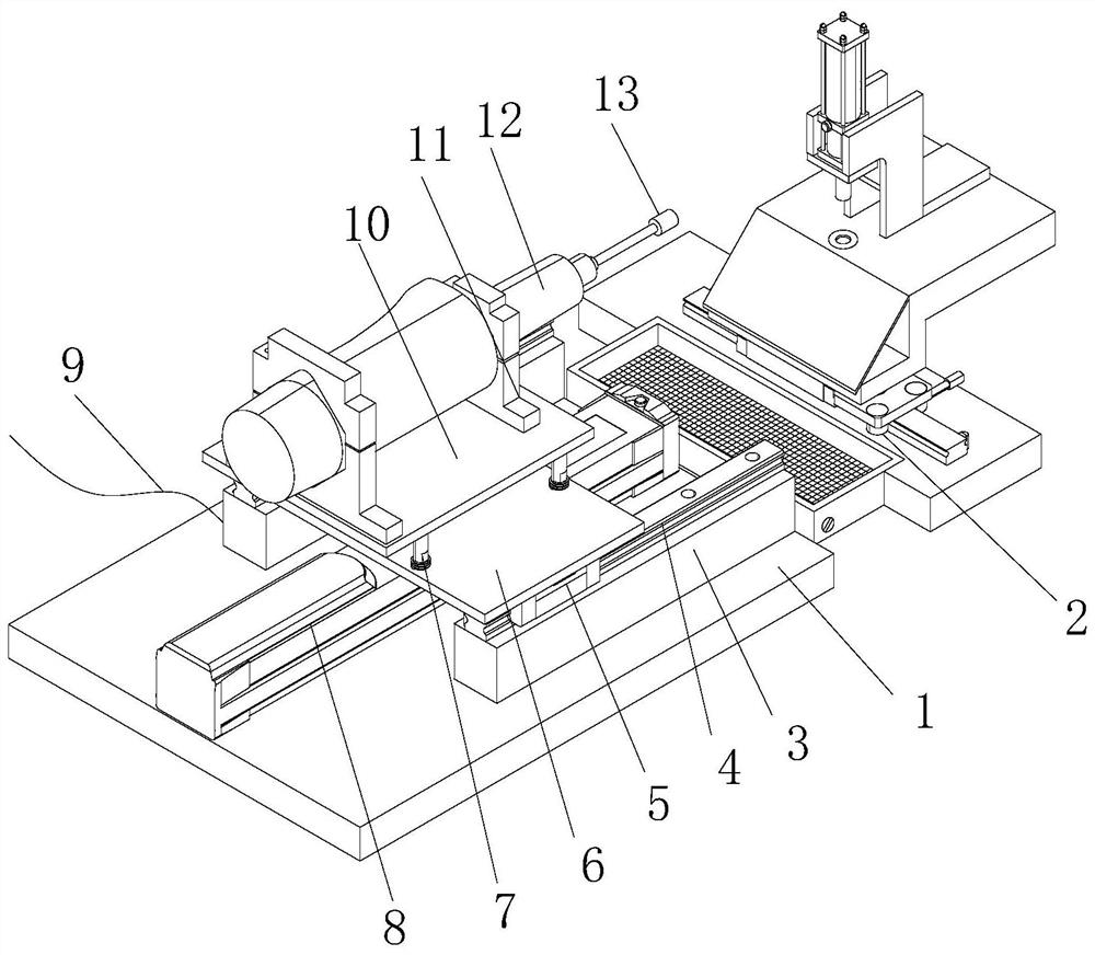
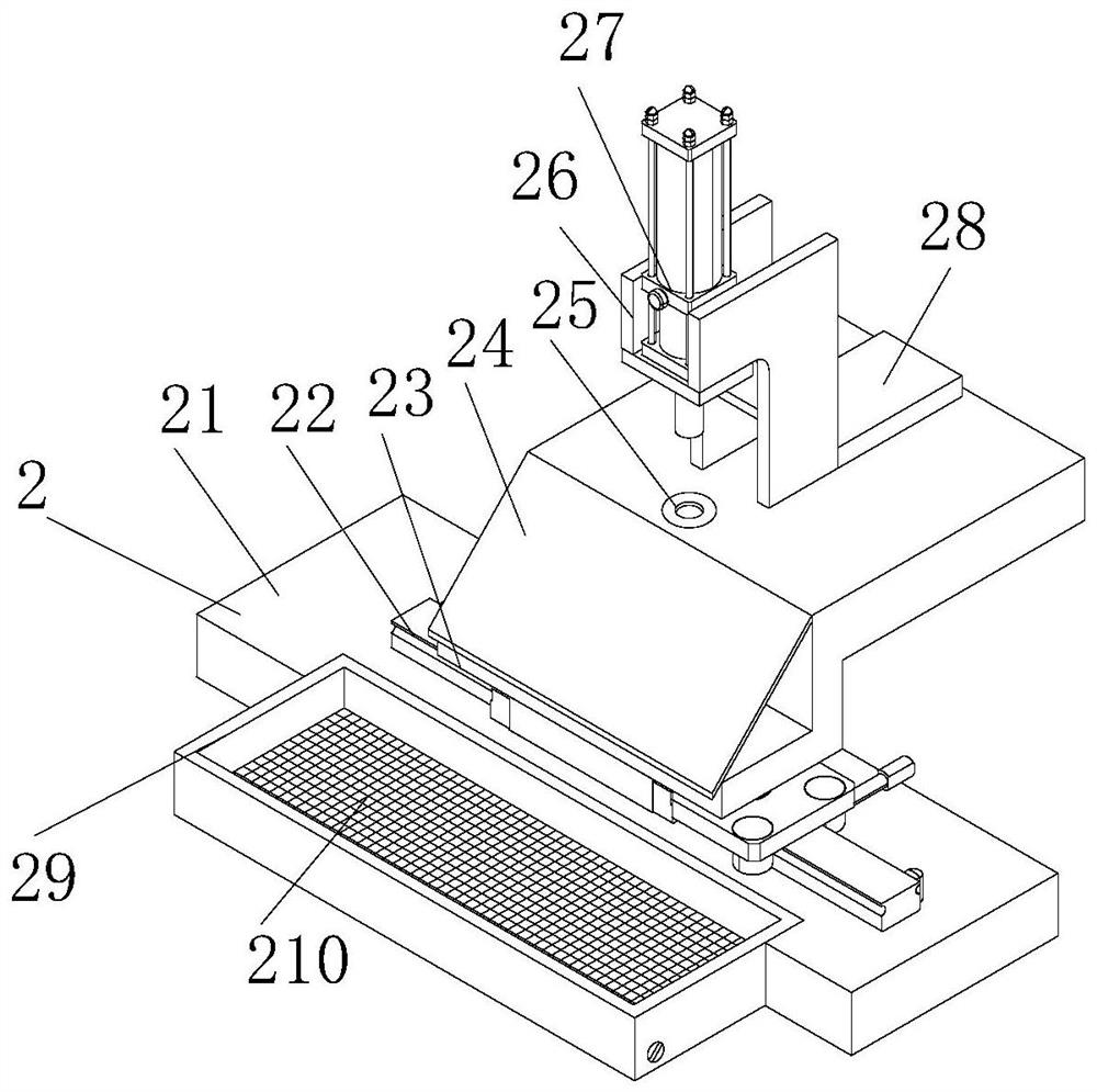
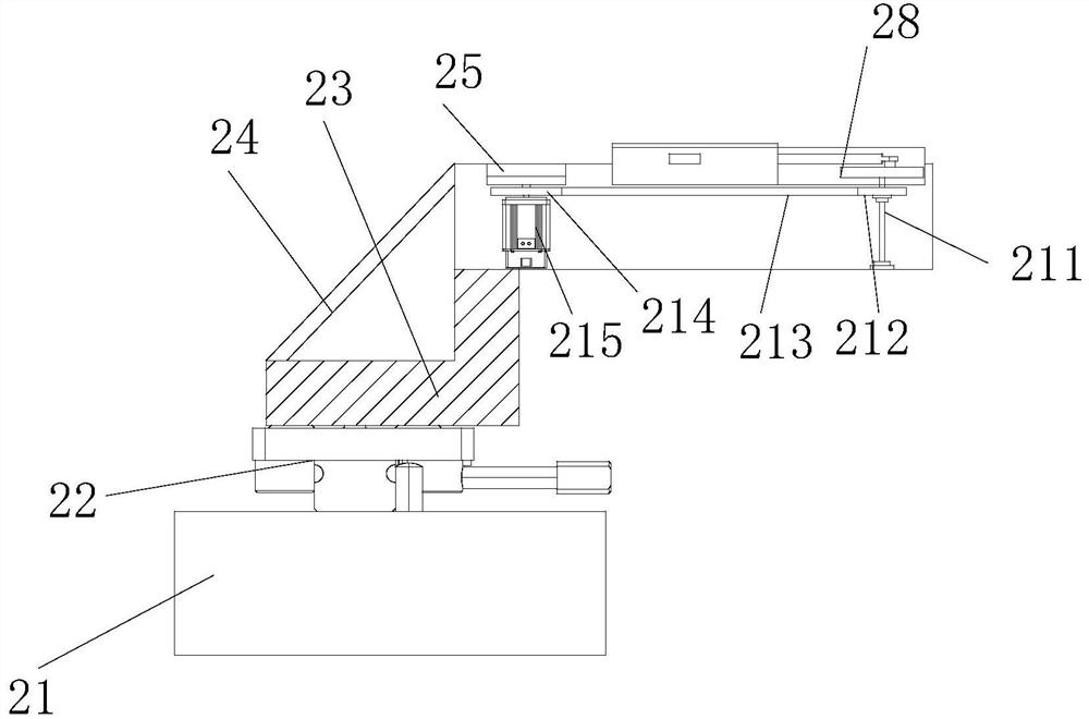
[0026] The following will be combined with Figure 1-7 The present invention is described in detail, and the technical solutions in the embodiments of the present invention are clearly and completely described. Apparently, the described embodiments are only some of the embodiments of the present invention, not all of them. Based on the embodiments of the present invention, all other embodiments obtained by persons of ordinary skill in the art without making creative efforts belong to the protection scope of the present invention.

[0027]The present invention provides an auxiliary bone grafting device for anterior cervical fusion surgery through improvement, including a load-bearing plate 1, an auxiliary processing device 2, a slide rail seat 3, a first slide rail 4, a first slide block 5, a mounting plate 6, Pillar 7, linear push rod 8, connecting wire 9, top plate 10, locking piece 11, grinding machine 12 and grinding head 13, slide rail seat 3 is fixed at the front and rear...


PUM

PropertyMeasurementUnit
Thicknessaaaaaaaaaa

Abstract

The invention discloses an anterior cervical fusion surgery auxiliary bone grafting device, which comprises a bearing plate, an auxiliary processing device, a slide rail seat and a sharpening machine, and is characterized in that the auxiliary processing device is mounted at the right end of the bearing plate, when an ilium is placed in an inner circular groove of a turntable, the ilium is pressed by a top cylinder and then is sharpened by a sharpening head, when the sharpening angle needs to be changed, a motor arranged in a supporting seat works, so that a sliding push block in a supporting mechanism on the back face is pushed out, meanwhile, a rotary disc rotates to change the ilium angle, then the sliding push block supports the back face of the ilium, then coping is conducted, the motor rotates reversely, the sliding push block retreats due to an arranged ratchet mechanism, and an air cylinder retreats after machining is completed; an elastic block in the sliding push block pops up under the acting force of a spring, the ilium falls into the cleaning tank filled with disinfection alcohol under pushing force to be manually cleaned, surface powder impurities fall into the bottom of the cleaning tank during soaking, the temperature facilitates rapid removal, the grinding efficiency is improved, and the auxiliary effect is better.

Description


Claims


Application Information

Patent Timeline
Owner FOURTH MILITARY MEDICAL UNIVERSITY
Why Eureka
Try Eureka