Nickel plating protection clamp and nickel plating protection method

A technology for protecting fixtures and fixtures, applied in the direction of electrolysis process, electrolysis components, etc., can solve the problems of uneven plating on the surface of the workpiece, affecting the performance of the workpiece, affecting the wear resistance and corrosion resistance of the workpiece, and improving the quality of electroplating. Guarantee Electroplating effect, the effect of improving the effect of use

Inactive Publication Date: 2022-02-18
蒋昊良
View PDF0 Cites 2 Cited by
  • Summary
  • Abstract
  • Description
  • Claims
  • Application Information

AI Technical Summary

Problems solved by technology

[0003] In the prior art, hangers or fixtures are generally used to fix square, frame-shaped and other large and irregularly shaped workpieces, such as molds or crankshafts; after the hangers or fixtures fix the workpieces, the plating solution in the area where the hangers or fixtures contact the workpieces The immersion ability is poor, so the coating in this area is shallow or even has no coating. After the workpiece is fully plated, it is necessary to repair the unplated area of ​​the workpiece;
[0004] In the prior art, the post-repair method is generally used to repair and electroplate the clamped area of ​​the workpiece; that is, to manually use the electroplating repair re-plating machine and electroplating solution to re-plate the unplated area of ​​the workpiece; only after repair can it meet the requirements of GB / T13913- 92 standard; but the thickness of the repaired electroplating layer is different from the thickness of the previous electroplating, which makes the surface of the workpiece electroplated unevenly, which affects the quality of the workpiece, and then affects the wear resistance and corrosion resistance of the workpiece, thus affecting the performance of the workpiece , such as the polarization generated when the crankshaft rotates;

Method used


Image

  • Nickel plating protection clamp and nickel plating protection method
  • Nickel plating protection clamp and nickel plating protection method
  • Nickel plating protection clamp and nickel plating protection method

Examples


Embodiment approach

[0056] As an embodiment of the present invention, the upper expansion mechanism 2 includes an upper expansion rod 21, a No. 1 connecting rope 22 and a No. 1 motor 23; the end surface of the upper support plate 1 close to the upper clamp 3 is evenly provided with sliding grooves 24 The sliding groove 24 is arranged radially; the upper spreading rod 21 is evenly connected with the outer surface of the upper fixture 3, and the upper spreading rod 21 is slidably connected in the corresponding sliding groove 24, and the other end of the upper spreading rod 21 It is flush with the lower end surface of the upper fixture 3; the No. 1 motor 23 is fixedly connected with the upper support plate 1 and the output shaft is facing downward; the upper expansion rod 21 is fixedly connected with a No. 1 connecting rope 22 and the other end of the connecting rope is connected with the No. 1 The output shaft of the motor 23 is fixedly connected;

[0057] The lower stretching mechanism 5 comprises...

Embodiment 1

[0083] A nickel-plated protection fixture comprising:

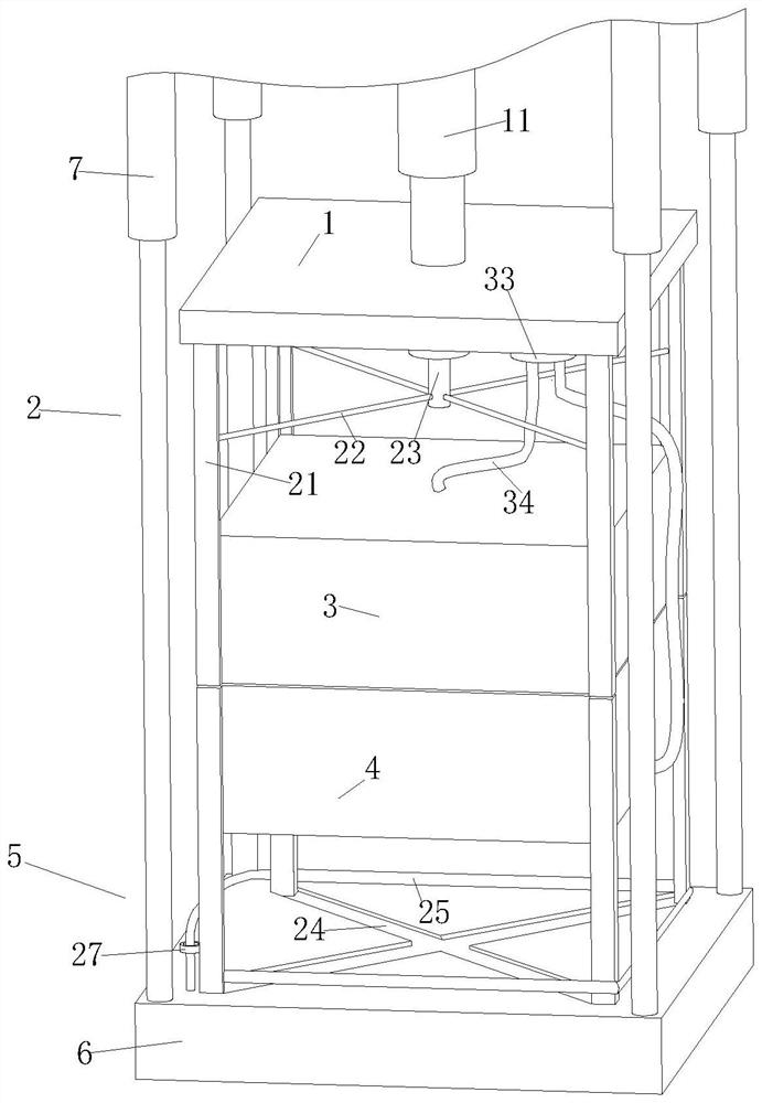
[0084] The upper support plate 1, the upper end surface of the upper support plate 1 is fixedly connected with the No. 1 elevating rod 11;

[0085] The upper expansion mechanism 2 is connected to the lower end surface of the upper support plate 1;

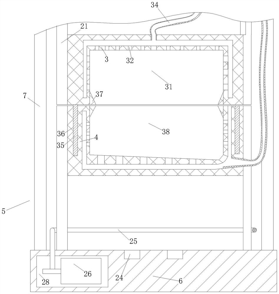
[0086] The upper fixture 3, the upper fixture 3 is located below the upper stretching mechanism 2 and connected with the upper stretching mechanism 2, the lower end surface of the upper fixture 3 is provided with an upper wrapping groove 31; the upper wrapping groove 31 fits the upper half of the electroplating workpiece, and the upper wrapping groove 31 is used to clamp the upper part of the electroplating workpiece;

[0087] The lower fixture 4, the lower fixture 4 is located below the upper fixture 3, and the upper end of the lower fixture 4 is provided with a lower wrapping groove 38; the lower wrapping groove 38 fits the lower half of the electroplating workpiece, and th...

Embodiment 2

[0107] Compared with embodiment 1, the difference is:

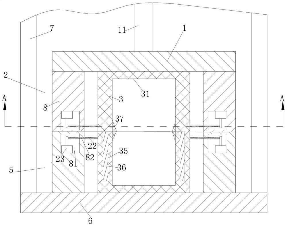
[0108] In this embodiment, the upper stretching mechanism 2 includes an upper stretching block 8; the upper stretching block 8 surrounds the upper clamp 3, and the upper stretching block 8 is fixedly connected with the upper support plate 1; the upper clamp 3 and the upper stretching There is a gap between the blocks 8; the upper stretching block 8 is provided with an annular groove 81 and the No. 1 motor 23 is installed in the upper stretching block 8; the inner side wall of the annular groove 81 is evenly provided with a sealing groove 82; the sealing groove 82 runs through Stretching block; the end of the upper fixture 3 close to the lower fixture 4 is evenly connected with a No. 1 connecting rope 22; the number of the No. 1 connecting rope 22 is the same as that of the sealing groove 82 and after the No. 1 connecting rope 22 passes through the corresponding sealing groove 82 Winding on the output shaft of No. 1 motor ...


PUM


Abstract

The invention relates to the technical field of electroplating, in particular to a nickel plating protection clamp and a nickel plating protection method. The nickel plating protection clamp comprises an upper supporting plate, wherein the upper end face is fixedly connected with a first lifting rod; an upper opening mechanism connected with the lower end face of the upper supporting plate; an upper clamp located below the upper opening mechanism and connected with the upper opening mechanism, wherein a wrapping groove is formed in the lower end face of the upper clamp, and the wrapping groove is attached to the upper half portion of the electroplated workpiece and used for clamping the upper half portion of the electroplated workpiece; and a lower clamp located below the upper clamp, wherein a wrapping groove is formed in the upper end face of the lower clamp. According to the nickel plating protection clamp, the upper clamp and the lower clamp are used for clamping the upper half portion and the lower half portion of the workpiece respectively, then the workpiece is placed in electroplating liquid for electroplating, half of the workpiece is electroplated in two times of electroplating, and therefore the electroplated area is not clamped by the clamp in the electroplating process, and the originally clamped area is electroplated as well; and therefore, the electroplating quality of the electroplated area of the workpiece is improved, and the using effect of the electroplating clamp is improved.

Description

technical field [0001] The invention relates to the technical field of electroplating, in particular to a nickel plating protection fixture and a nickel plating protection method. Background technique [0002] Electroplating is the process of plating a thin layer of other metals or alloys on the surface of certain metals using the principle of electrolysis. It is a process of using electrolysis to attach a layer of metal film to the surface of metal or other material parts to prevent metal oxidation ( Such as rust), improve wear resistance, conductivity, reflectiveness, corrosion resistance and enhance the appearance, etc. During electroplating, clamps are generally used to hold the workpiece and then the workpiece is immersed in the electroplating solution for electroplating; [0003] In the prior art, hangers or fixtures are generally used to fix square, frame-shaped and other large and irregularly shaped workpieces, such as molds or crankshafts; after the hangers or fixtu...

Claims


Application Information

Patent Timeline
Patent Type & Authority Applications(China)
IPC IPC(8): C25D17/06C25D5/02C25D3/12
CPCC25D17/06C25D5/02C25D3/12
Inventor 蒋昊良孙坤磊
Owner 蒋昊良
Why Eureka
Try Eureka