An anchor-casting integrated structure and construction method of plastic concrete underground diaphragm wall

A technology of underground diaphragm wall and plastic concrete, which is applied in the direction of foundation structure engineering, sheet pile wall, sea area engineering, etc. It can solve the problems that affect the normal construction of the excavation area, low strength, and reduce the probability of water flow, so as to improve the connection effect , Reduce the probability of fracture and facilitate construction

Active Publication Date: 2022-06-03
CHINA UNIV OF MINING & TECH
View PDF7 Cites 0 Cited by
  • Summary
  • Abstract
  • Description
  • Claims
  • Application Information

AI Technical Summary

Problems solved by technology

[0003] In the prior art, in order to achieve temporary waterproofing, most plastic concrete cut-off walls are used. There is no steel bar inside the plastic concrete cut-off wall, and its strength is low, so it can follow the coordinated deformation of the soil, making the gap between the cut-off wall and the soil Less likely to create gaps, thus reducing the chance of water flow through
However, the existing plastic concrete cut-off walls still have problems. When the excavation area is excavated, the deformation of the soil will drive the deformation of the cut-off wall, but the cut-off wall still inevitably produces shear compared with the soil. The gap between the anti-seepage wall and the soil will cause the water flow to flow around the excavation area, which will affect the normal construction of the excavation area.

Method used


Image

  • An anchor-casting integrated structure and construction method of plastic concrete underground diaphragm wall
  • An anchor-casting integrated structure and construction method of plastic concrete underground diaphragm wall
  • An anchor-casting integrated structure and construction method of plastic concrete underground diaphragm wall

Examples


Embodiment Construction

[0035] The technical solutions in the embodiments of the present invention will be clearly and completely described below with reference to the accompanying drawings in the embodiments of the present invention. Obviously, the described embodiments are only a part of the embodiments of the present invention, rather than all the embodiments. Based on the embodiments of the present invention, all other embodiments obtained by those of ordinary skill in the art without creative efforts shall fall within the protection scope of the present invention.

[0036] In order to make the above objects, features and advantages of the present invention more clearly understood, the present invention will be described in further detail below with reference to the accompanying drawings and specific embodiments.

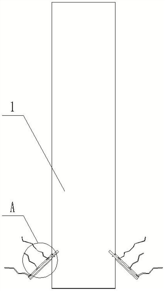
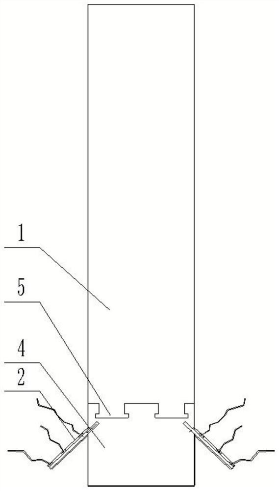
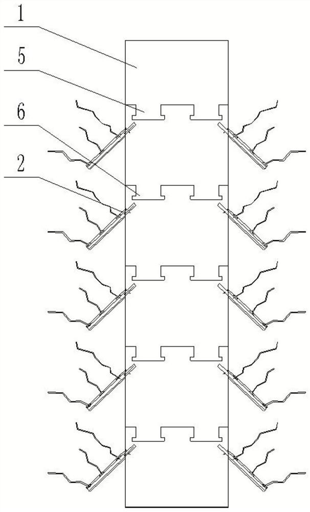
[0037] The present invention provides an integrated structure of plastic concrete underground diaphragm wall anchoring and casting, comprising an anti-seepage pit 1, an anti-seepage wal...


PUM


Abstract

The invention discloses an anchoring-casting integrated structure and construction method for plastic concrete underground continuous walls, which include an anti-seepage pit, an anti-seepage wall is poured in the anti-seepage pit, and a number of drill holes are sequentially opened on the side wall of the anti-seepage pit from top to bottom. The hole is located on the side of the anti-seepage pit away from the excavation area, and a reinforcement part is arranged in the drill hole, and the reinforcement part is fixed with the anti-seepage wall; connection, the liquid inlet of the hollow anchor is located in the anti-seepage pit, the liquid outlet of the hollow anchor is located in the borehole, and the opening of the liquid outlet of the hollow anchor is upward; A reinforcement; the connection between the hollow anchor rod and the anti-seepage wall is provided with a second reinforcement for strengthening the connection. The invention can improve the connection effect between the anti-seepage wall and the soil, and when the deformation of the soil further drives the deformation of the anti-seepage wall, the probability of gaps between the anti-seepage wall and the soil is reduced, thereby reducing the probability of water flowing around the excavation area .

Description

technical field [0001] The invention relates to the technical field of building construction, in particular to a plastic concrete underground diaphragm wall anchor-grouting integrated structure and construction method. Background technique [0002] The underground diaphragm wall is a continuous hole made with mud solid wall in the loose permeable foundation or earth-rock dam (weir) dam body, and concrete is poured under the mud or other anti-seepage materials are backfilled. Impermeable wall. [0003] In the prior art, in order to achieve temporary waterproofing, most of the plastic concrete seepage-proof walls are used. There are no steel bars inside the plastic concrete seepage-proof walls, and their strength is low. It is not easy to create gaps, thus reducing the chance of water flow through. However, the existing plastic concrete anti-seepage wall still has problems. When the excavation area is excavated, the soil body is deformed, which in turn drives the deformation...

Claims


Application Information

Patent Timeline
Patent Type & Authority Patents(China)
IPC IPC(8): E02D5/18E02D19/18E02D15/02E02D5/76E02B3/16
CPCE02D5/18E02D19/18E02D19/185E02D15/02E02D5/76E02B3/16E02D2250/0023E02D2250/003E02D2600/20E02D2600/30
Inventor 刘日成李树忱刘振国蔚立元刘尚刘兰富刘枫王蓥森
Owner CHINA UNIV OF MINING & TECH
Why Eureka
Try Eureka