Fabricated steel-concrete composite shear wall and construction method
A technology for combining shear walls and concrete, applied to walls, buildings, building reinforcements, etc., can solve the problems of easy deformation, large component size, and high cost
- Summary
- Abstract
- Description
- Claims
- Application Information
AI Technical Summary
Problems solved by technology
Method used
Image
Examples
Embodiment 1
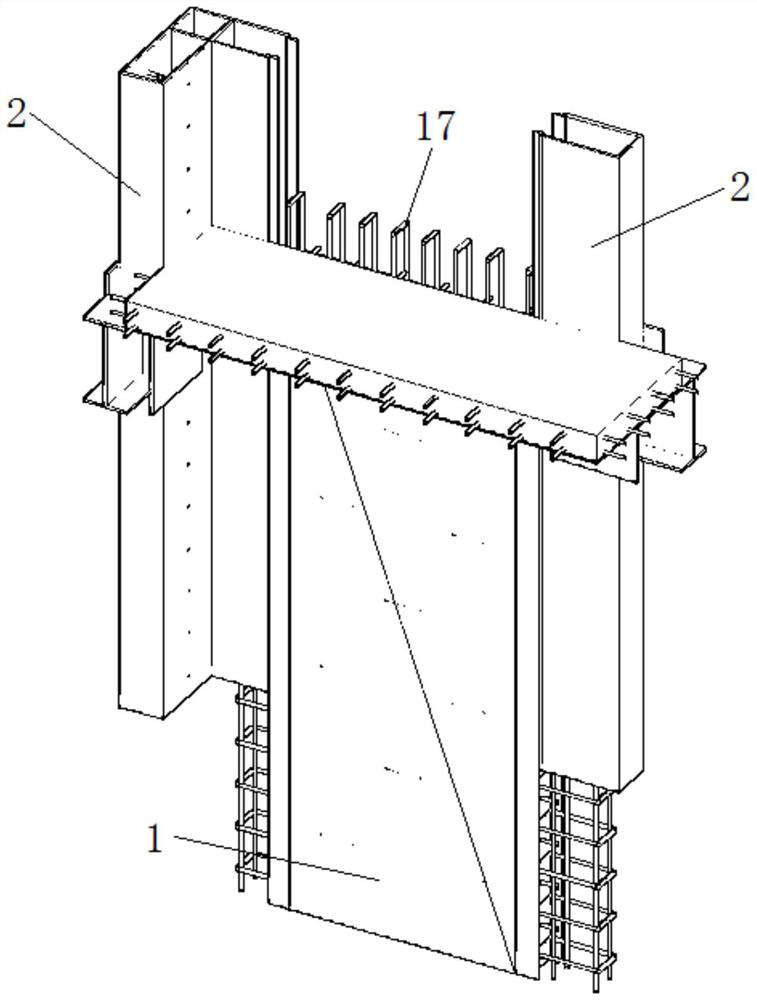
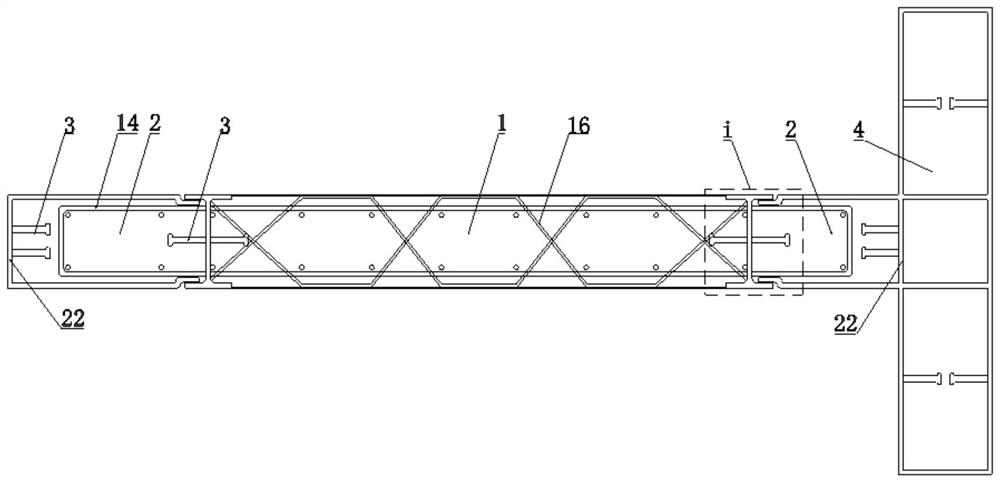
[0022] Such as figure 1 , 2 , 3, 4, 5, 6, and 7, a prefabricated steel concrete composite shear wall includes an intermediate wall 1 and two end walls 2, and the intermediate wall 1 is located at the two ends between the wall 2;
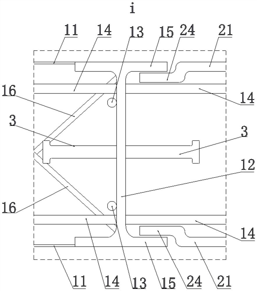
[0023] The middle wall body 1 includes two vertical and facing middle panels 11, two frame panels 12 are connected between the two middle panels 11, the frame panels 12 are arranged vertically, and the two The frame boards 12 are respectively close to the two end walls 2, and the two middle panels 11 and the two frame boards 12 enclose the middle pouring area. There are several shear studs 3 in the direction;
[0024] Several first vertical reinforcement bars 13 and several transverse reinforcement bars 14 are distributed in the intermediate pouring area, the first vertical reinforcement bars 13 and the horizontal reinforcement bars 14 are welded to each other, and the first vertical reinforcement bars 13 are arranged vertically , the transverse ...
Embodiment 2
[0044] A construction method for the fabricated steel-concrete composite shear wall described in Embodiment 1, comprising:
[0045] Step 1. Prefabricated intermediate pouring system
[0046] Step 1.1, welding all the first vertical steel bars 13 and the transverse steel bars 14 to form two steel mesh sheets, during which the truss steel bars 16 are set on the two steel mesh sheets; The two ends of the transverse steel bars 14 are respectively bent towards the other said reinforcement mesh sheet, and the rectangular support frame is welded out, and the reinforcement mesh sheet and the truss reinforcement 16 form a reinforcement cage;
[0047] Step 1.2. Set the perforations 12a on the frame board 12 corresponding to each of the rectangular support frames, and then respectively set the two frame boards 12 on the left and right sides of the reinforcement cage, so that the frame boards 12 is kept against the first vertical steel bar 13 located on the outermost side;
[0048] Fina...
Embodiment 3
[0058] A connection structure between a prefabricated steel-concrete composite shear wall and a floor slab, combining Figure 8 It can be seen that, including the fabricated steel-concrete composite shear wall of Embodiment 1, the lower part of the middle wall 1 extends downward beyond the lower edge of the end wall 2, and the end wall 2 The upper part extends upwards and exceeds the upper edge of the intermediate wall 1, and the upper part of the intermediate wall 1 is bound with a connecting steel bar 17, the connecting steel bar 17 is rectangular, and the lower part of the connecting steel bar 17 is connected to the first The upper end of the vertical steel bar 13 is bound, and the upper part of the connecting steel bar 17 protrudes upwards from the middle wall 1;
[0059] The outer wall of the end wall 2 is fixed with a floor pouring support, the floor pouring support is close to the upper end of the middle wall 1, and also includes a floor pouring bottom formwork, the edg...
PUM
 Abstract
Description
Claims
Application Information
 - R&D
- Intellectual Property
- Life Sciences
- Materials
- Tech Scout
- Unparalleled Data Quality
- Higher Quality Content
- 60% Fewer Hallucinations
Browse by: Latest US Patents, China's latest patents, Technical Efficacy Thesaurus, Application Domain, Technology Topic, Popular Technical Reports.
© 2025 PatSnap. All rights reserved.Legal|Privacy policy|Modern Slavery Act Transparency Statement|Sitemap|About US| Contact US: help@patsnap.com


