Unmanned aerial vehicle-mounted ammunition launching platform

A launch platform and unmanned aerial vehicle technology, applied in launch devices, aircraft parts, transportation and packaging, etc., can solve the problem of inconvenient combat missions for unmanned ammunition launch platforms, and achieve the effect of ensuring real-time and high efficiency

Pending Publication Date: 2022-02-18
江苏溧航航空科技有限公司
View PDF0 Cites 1 Cited by
  • Summary
  • Abstract
  • Description
  • Claims
  • Application Information

AI Technical Summary

Problems solved by technology

[0005] The invention provides an unmanned aerial vehicle-borne ammunition launching platform, which solves the problem that...

Method used


Image

  • Unmanned aerial vehicle-mounted ammunition launching platform
  • Unmanned aerial vehicle-mounted ammunition launching platform
  • Unmanned aerial vehicle-mounted ammunition launching platform

Examples


no. 1 example

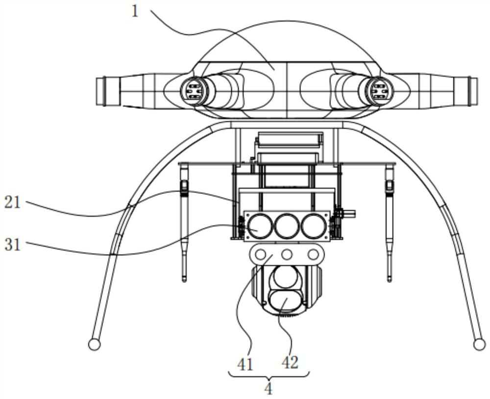
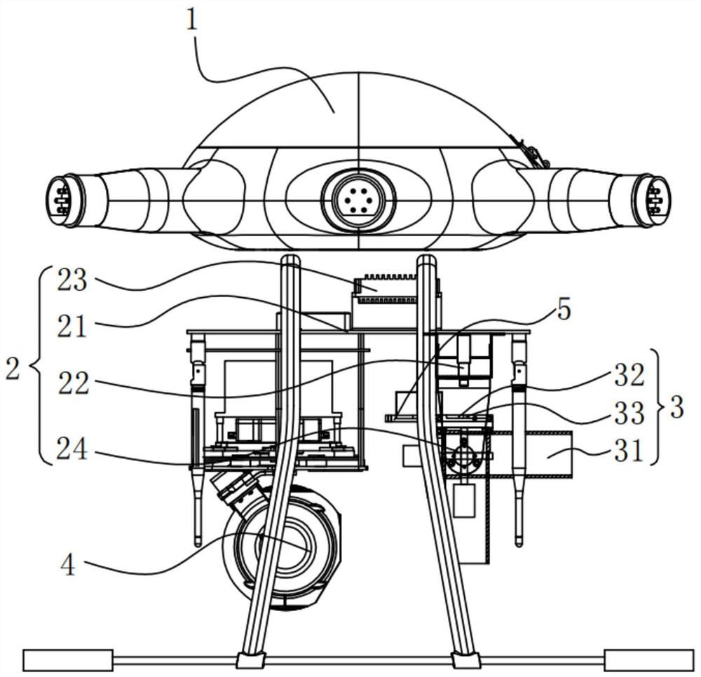
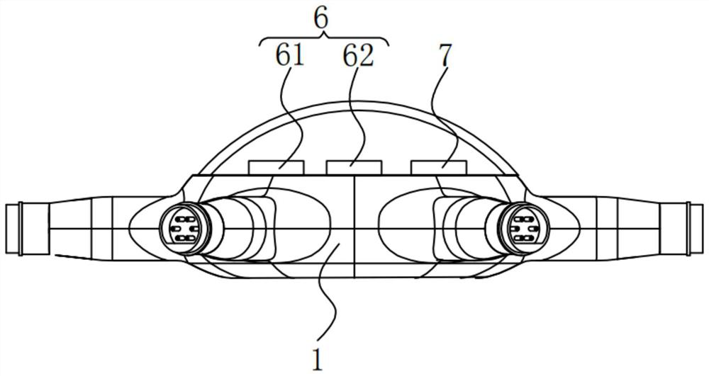
[0041] Please refer to figure 1 , figure 2 , image 3 and Figure 4 ,in, figure 1 A schematic structural diagram of the first embodiment of the UAV-carried ammunition launching platform provided by the present invention; figure 2 for figure 1 The schematic structural diagram of the side view part of the UAV shown; image 3 for figure 1 Schematic diagram of the structure of the internal part of the UAV shown; Figure 4 The overall system diagram of the control launch of the unmanned aerial vehicle-borne ammunition launch platform provided by the present invention. The UAV-carried ammunition launch platform includes: UAV 1;

[0042] The pan / tilt 2 is fixed on the bottom of the UAV 1. The pan / tilt 2 includes a rotating bracket 21. The rotating bracket 21 is provided with a drive motor 22 and a drive control module 23, and the rotating bracket One side of 21 is fixedly connected with an angle sensor 24 for cooperating with the driving control module 23 to control the ro...

no. 2 example

[0071] Please refer to Figure 4 and Figure 5 , based on the UAV-based ammunition launch platform provided in the first embodiment of the present application, the second embodiment of the present application proposes another UAV-based ammunition launch platform. The second embodiment is only a preferred mode of the first embodiment, and the implementation of the second embodiment will not affect the independent implementation of the first embodiment.

[0072] Specifically, the difference between the UAV-based ammunition launching platform provided in the second embodiment of the present application is that the UAV-based ammunition launching platform also includes

[0073] The ground hand-held transceiver 8 used to control the UAV 1 that cooperates with the main control module 7, the ground hand-held transceiver 8 includes a housing 81, and the outer surface of the housing 81 is provided with multiple A control panel 82 for a control switch;

[0074] The flight of the whole...


PUM


Abstract

The invention provides an unmanned aerial vehicle-mounted ammunition launching platform. The unmanned aerial vehicle-mounted ammunition launching platform comprises an unmanned aerial vehicle, and a cradle head, wherein the cradle head is fixed to the bottom of the unmanned aerial vehicle and comprises a rotating support, the rotating support is provided with a driving motor and a driving control module, and an angle sensor used for being matched with the driving control module to control the rotating angle of the rotating support is fixedly connected to one side of the rotating support. The unmanned aerial vehicle-mounted ammunition launching platform is provided with an ammunition launcher which can launch standard tear bombs, stun grenades, smoke bombs and the like, the ammunition launcher is installed on the unmanned aerial vehicle, the unmanned aerial vehicle serves as a flying platform, the unmanned aerial vehicle enters a battlefield through ground remote control, then a target to be avoided is searched, locked and tracked through an aiming assembly, and then the target is hit through a triple launching container, so that the target can be hit rapidly and accurately, and a specified task can be completed rapidly and accurately.

Description

technical field [0001] The invention relates to the technical field of unmanned aerial vehicle pyrotechnic control, in particular to an unmanned aerial vehicle-carrying ammunition launching platform. Background technique [0002] Unmanned aerial vehicle is referred to as "unmanned aerial vehicle", and the English abbreviation is "UAV". [0003] In the prior art, although the UAV flight application technology and the ammunition launching technology are mature, the combination of the UAV and the ammunition launching technology makes the operation of the strike system very complicated, and it is inconvenient to quickly lock and complete the strike on the target. It is inconvenient to quickly complete the designated strike mission. [0004] Therefore, it is necessary to provide an unmanned aerial vehicle-borne ammunition launching platform to solve the above technical problems. SUMMARY OF THE INVENTION [0005] The invention provides an unmanned aerial vehicle-carrying amm...

Claims


Application Information

Patent Timeline
IPC IPC(8): F41F1/00B64D1/06
CPCF41F1/00B64D1/06
Inventor 桂菁李继军孙青谈嘉栋陈程
Owner 江苏溧航航空科技有限公司
Why Eureka
Try Eureka