
Disconnecting link fastening device

A technology of fastening device and knife switch, which is applied in the direction of contacts, electrical components, electric switches, etc., can solve problems such as power grid disconnection, loose contact between static contacts and moving contacts, and influence of users' power consumption, so as to ensure stability , The effect of preventing contact loosening

Pending Publication Date: 2022-02-18
GUANGDONG POWER GRID CO LTD +1
View PDF0 Cites 0 Cited by
  • Summary
  • Abstract
  • Description
  • Claims
  • Application Information

AI Technical Summary

Problems solved by technology

However, the isolation switch is the most widely used switch in high-voltage switchgear, and faults occur frequently. This is because the contact between the static contact and the moving contact will loosen after the isolation switch is used repeatedly, resulting in the disconnection of the power grid. , at this time, the maintenance personnel need to cut off the power for maintenance, which has a great influence on the power consumption of users

Method used


Image

  • Disconnecting link fastening device
  • Disconnecting link fastening device
  • Disconnecting link fastening device

Examples


Embodiment 1

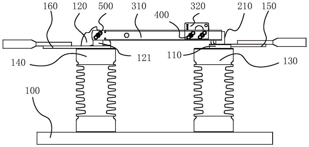
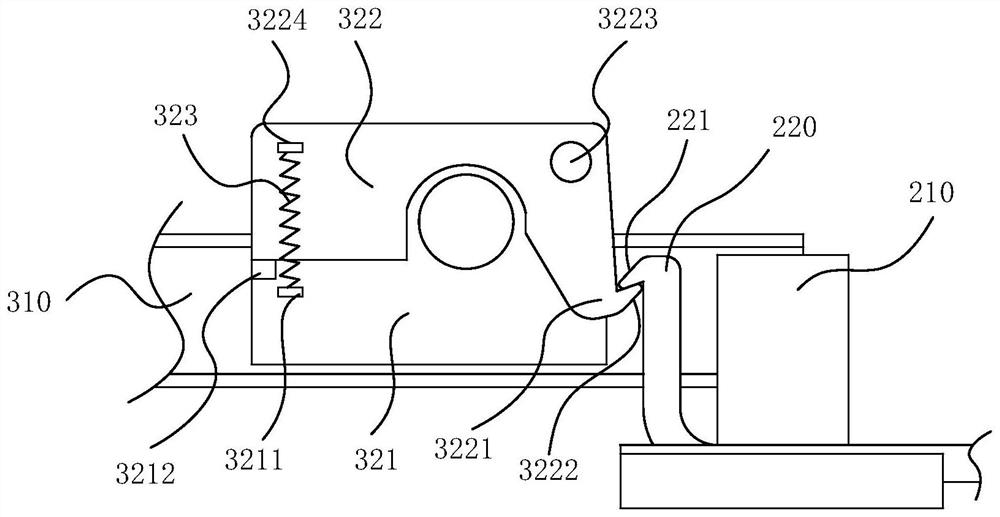
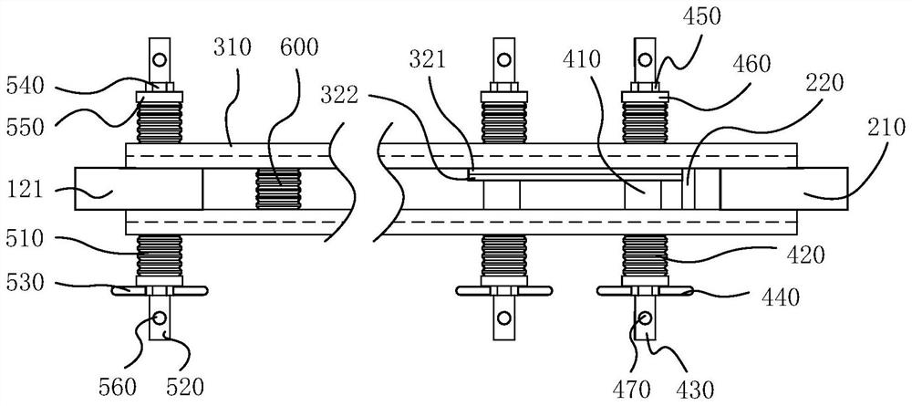
[0053] refer to figure 1As shown, this embodiment provides a knife gate fastening device, including a knife gate base 100, a static contact, a moving contact and a first clamping mechanism 400, and the knife gate base 100 is provided with a fixed seat 110 and a hinged seat 120, the static contact includes a static contact piece 210 and a first buckle mechanism, the static contact piece 210 and the first buckle mechanism are both arranged on the fixed seat 110, the moving contact includes a moving contact piece 310, and the moving contact piece 310 is provided with Two and symmetrically arranged, the first end of the movable contact piece 310 is hinged with the hinge seat 120, and the second end of the movable contact piece 310 is provided with a second buckle mechanism 320 that can be engaged with the first buckle mechanism. When the mechanism is engaged with the second buckle mechanism 320, the two side surfaces of the static contact piece 210 respectively abut against the in...

Embodiment 2

[0072] The first clamping mechanism 400 in the knife switch fastening device provided in this embodiment is different from Embodiment 1. In this embodiment, refer to Figure 6 As shown, the first fastening rod 430 is integrally formed with the first fastening member 440, and the first through hole of the movable contact piece 310 away from the first fastening member 440 is provided with an external thread connected to the second end of the first fastening rod 430. Internal thread for mating connections. Specifically, the second end of the first fastening rod 430 passes through the first elastic member 420, the movable contact piece 310 close to the first fastening part 440, the limit sleeve 410, the fixing plate 321 and the 440 of the moving contact piece 310 and is screwed to the moving contact piece 310 away from the first fastener 440 .

[0073] Further, the second end of the first fastening rod 430 is provided with a first pin hole, and a limit pin is inserted into the fi...

Embodiment 3

[0076] The first clamping mechanism 400 in the knife switch fastening device provided in this embodiment is different from Embodiment 1 and Embodiment 2. In this embodiment, refer to Figure 7 As shown, the first fastening rod 430 can be a bolt, and the threaded end of the bolt is sequentially passed through the first elastic member 420 on one side, the movable contact piece 310 on one side, the fixed plate 321, the limit sleeve 410, and the The moving contact piece 310 and the first elastic member 420 on the other side are screwed to the first fastening member 440 .

[0077] Further, the threaded end of the bolt is provided with a first pin hole, and a limit pin is inserted into the first pin hole to prevent the first fastener 440 from detaching from the first fastening rod 430 .

[0078] Other structures of the knife gate fastening device provided in this embodiment are the same as those in Embodiment 1, and will not be described in detail here.


PUM


Abstract

The invention belongs to the technical field of power distribution equipment, and discloses a disconnecting link fastening device, the disconnecting link fastening device comprises a disconnecting link base, a static contact, a moving contact and a first clamping mechanism, the disconnecting link base is provided with a fixed seat and a hinge seat, the static contact comprises a static contact piece and a first buckling mechanism, the static contact piece and the first buckling mechanism are both arranged on the fixed seat, the moving contact comprises two moving contact pieces which are symmetrically arranged, the first ends of the moving contact pieces are hinged to the hinge seat, the second ends of the moving contact pieces are provided with second buckling mechanisms which can be connected with the first buckling mechanism in a clamped mode, and the first clamping mechanism is arranged on the moving contact. According to the disconnecting link fastening device provided by the invention, the two side surfaces of the static contact piece respectively abut against the inner side surfaces of the two movable contact pieces, and the first buckling mechanism is clamped with the second buckling mechanism, so that the static contact piece is effectively prevented from being separated from the movable contact pieces; and the two movable contact pieces clamp the static contact piece through the first clamping mechanism, so that the contact looseness between the static contact and the movable contact is effectively prevented.

Description

technical field [0001] The invention relates to the technical field of power distribution equipment, in particular to a knife switch fastening device. Background technique [0002] With the continuous development of society and the rapid development of the power supply industry, users have higher and higher demands on the quality of power supply. Planned power outages and fault power outages have a great impact on users' electricity consumption, and fault power outages have uncontrollable factors and uncertainties, and cannot be restored in time, seriously affecting user experience. [0003] At present, with the upgrading of power equipment and the improvement of manufacturing technology and operation level, a large number of maintenance-free electrical equipment has been put into operation, which greatly reduces the failure and the maintenance workload. However, the isolation switch is the most widely used switch in high-voltage switchgear, and faults occur frequently. Thi...

Claims


Application Information

Patent Timeline
IPC IPC(8): H01H21/12H01H21/14H01H21/18H01H21/54H01H1/52
CPCH01H21/12H01H21/14H01H21/18H01H21/54H01H1/52
Inventor 魏兴元郑凯成
Owner GUANGDONG POWER GRID CO LTD
Learn More