Method for manufacturing stator frame of hydraulic generator

A technology for hydroelectric generators and stator bases, which is applied in the manufacture of stator/rotor bodies, etc., which can solve problems such as high cost, long production cycle, and complicated process, and achieve the effects of cost saving, workload reduction, and simple process

Active Publication Date: 2022-02-18
DEYANG JIUDING ELECTRIC CO LTD
View PDF5 Cites 0 Cited by
  • Summary
  • Abstract
  • Description
  • Claims
  • Application Information

AI Technical Summary

Problems solved by technology

[0005] The purpose of the present invention is: in order to solve the problems of complicated process, high cost and long productio

Method used


Image

  • Method for manufacturing stator frame of hydraulic generator
  • Method for manufacturing stator frame of hydraulic generator
  • Method for manufacturing stator frame of hydraulic generator

Examples


Embodiment 1

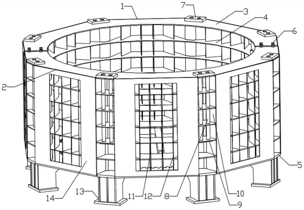
[0035] Such as figure 1 As shown, this embodiment provides a method for manufacturing a stator frame of a hydroelectric generator. The stator frame includes a first frame 1 and a second frame 2, and the horizontal sections of the first frame 1 and the second frame 2 are equal. Being semicircular, the manufacturing method of the stator frame includes the following steps:

[0036] Step S1: Process all the parts, reserve a 20mm cutting allowance for the inner circle of each layer of ring plates, and reserve a 3mm welding shrinkage allowance for the outer circle;

[0037] Step S2: Assemble and weld the first frame 1 and the second frame 2 respectively, perform shot blasting coating on the inside of the first frame 1 and the second frame 2 that will form a sealed chamber, and then assemble other components to form a seal Chamber;

[0038] Step S3: connecting the first frame 1 and the second frame 2 to form a complete circle;

[0039] Step S4: uniformly welding a plurality of sup...

Embodiment 2

[0050] This embodiment is based on Embodiment 1 to further optimize the description of the present invention.

[0051] Further, the step S3 specifically includes: combining the first machine base 1 and the second machine base 2 into a complete circle by welding steel plates at the junction of the first machine base 1 and the second machine base 2 .

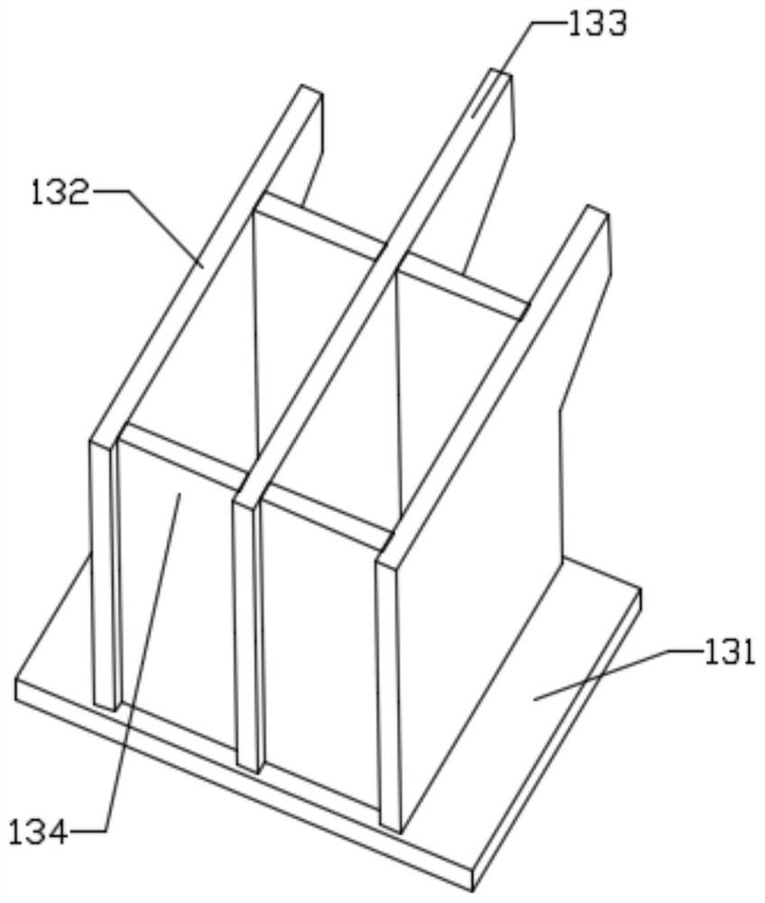
[0052] Such as image 3 As shown, the support member 13 in step S4 includes a first leg vertical plate 132, a second leg vertical plate 133, a leg rib plate 134 and a leg bottom plate 131, and the number of the first leg vertical plate 132 is two And parallel to each other, the second leg vertical board 133 is arranged in parallel between the two first leg vertical boards 132, and the leg rib 134 is vertically arranged between the two first leg vertical boards 132, and the two first leg vertical boards 132 are vertically arranged. One end of the leg vertical plate 132 , the second leg vertical plate 133 and the leg rib 134 are co...


PUM


Abstract

The invention discloses a method for manufacturing a stator frame of a hydro-generator, which relates to the technical field of hydro-generators, solves the technical problems of higher production cost and longer required production cycle, and comprises the following steps of: processing all parts, reserving 20mm cutting allowance on the inner circle of each layer of annular plate, and reserving 3mm welding shrinkage allowance on the outer circle of each layer of annular plate; welding the first machine base and the second machine base, and conducting shot blasting coating on the interior of a sealed cavity formed by the first machine base and the second machine base; connecting the first machine base and the second machine base into a whole circle; welding a supporting piece at the bottom of the stator base; performing stress relief and flaw detection treatment on the stator base; after the split surface allowance of the stator base is removed, combining the first base and the second base through the seam combining block; cutting the inner circle allowance of each layer of annular plate; checking and marking the stator base; and conducting shot blasting and paint spraying on the first machine base and the second machine base. The method has the advantages of being simple in process, small in workload and short in production period.

Description

technical field [0001] The invention relates to the technical field of hydroelectric generators, and in particular to a method for manufacturing a stator frame of a hydroelectric generator. Background technique [0002] The stator of the hydro-generator is the static part of the hydro-generator, which is composed of the frame, iron core, winding, copper ring and foundation screw. The base is mainly used to fix the iron core, which is circular or polygonal. Small-capacity hydro-generators mostly use cast iron round bases, or box-shaped bases welded with steel plates. The bases of large and medium-capacity hydro-generators It is welded and assembled by steel plates. The forces acting on the base include: the tangential force generated by the rated torque during operation and the radial force caused by the thermal expansion of the iron core; the tangential force generated by the short-circuit torque when the stator winding is short-circuited and the two One-way magnetic pull c...

Claims


Application Information

Patent Timeline
IPC IPC(8): H02K15/02B23P15/00
CPCH02K15/02B23P15/00Y02P70/50
Inventor 唐骁林刚舒学芳陈自生
Owner DEYANG JIUDING ELECTRIC CO LTD
Why Eureka
Try Eureka