Supercharge Your Innovation With Domain-Expert AI Agents!

Boost chopper circuit arrangement, power supply and method for boosting input voltage

Technology of a circuit device, chopper, applied in the field of power supply

Pending Publication Date: 2022-02-18
PHOENIX CONTACT GMBH & CO KG
View PDF3 Cites 0 Cited by
  • Summary
  • Abstract
  • Description
  • Claims
  • Application Information

AI Technical Summary

Problems solved by technology

However, this requires a pole-changing circuit, thus closing the loop

Method used


Image

  • Boost chopper circuit arrangement, power supply and method for boosting input voltage
  • Boost chopper circuit arrangement, power supply and method for boosting input voltage
  • Boost chopper circuit arrangement, power supply and method for boosting input voltage

Examples


Embodiment Construction

[0059] This specification illustrates the principles of the present disclosure. Therefore, it should be understood that those skilled in the art will be able to conceive various design solutions, although not explicitly stated here, these design solutions embody the disclosed principles according to the present invention and are equally protected within the scope thereof.

[0060] The concept according to the invention is discussed using the example of a positive input voltage or a positive half-wave of an input AC voltage. In the case of negative input voltages or negative half-waves of the input AC voltage, the functions of the semiconductor switches of the step-up chopper circuit are reversed accordingly.

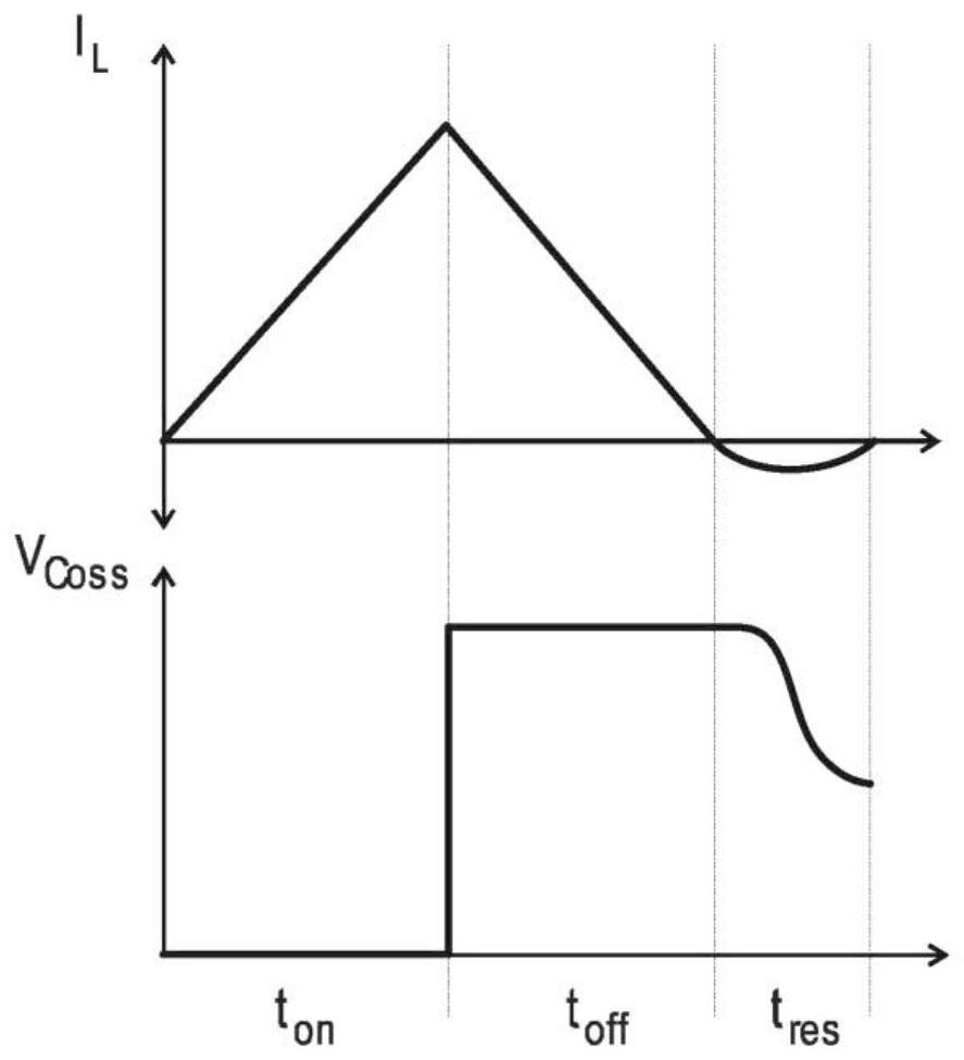
[0061] As mentioned above, there is a way to run a PFC circuit in boundary conduction mode (BCM). Time t for repeated magnetization inductance L; L1 on Constant over the sine half-wave of the AC mains voltage. This time is proportional to the power output of the switc...


PUM


Abstract

The invention relates to a boost chopper circuit arrangement (100) for an electrical consumer power supply, comprising a rectifier or pole-changing circuit (110), a dual-switch step-up chopper circuit (120) and a control unit (130) for controlling two semiconductor switches (S1, S2). According to the invention, a first semiconductor switch (S1) is connected in series with a measuring resistor (R1) and the control unit (130) is designed to determine, by calculation, a reference time period (Tref) in which the current (Ib) flowing through the measuring resistor (R1) during the switching period (Tperiod) should reach a predetermined current reference value (Iref), and to compare it with an actual time period (Tmessage) in which the current (Ib) flowing through the measuring resistor (R1) reaches a predetermined current reference value (Iref), and a time difference (Tdiff) is determined by depending on the result of a comparison between the calculated reference time period (Tmessref) and the actual time period (Tmessist). Depending on the time difference, the duration of the subsequent switching period (Tperiod) can be adjusted.

Description

technical field [0001] The invention relates to a step-up chopper circuit arrangement for a power supply of a consumer according to the preamble of claim 1 and a step-up chopper circuit arrangement according to the preamble of claim 2 . The invention also relates to a power supply having a boost chopper according to the invention. Boost choppers can be used in particular as power factor pre-regulators in switched-mode power supply units. The invention also relates to a method for boosting an input voltage in a power supply of a consumer. Background technique [0002] boost chopper (also known as a Hochsetzsteller or Hochsetzer) basic circuit is used in DC voltage converters where the input voltage is lower than the output voltage. The same principle is also used in low power switching power supplies, but using a transformer instead of a coil, which is also called a flyback converter (strictly speaking, not a transformer in this case, but one with two windings Choke coil...

Claims


Application Information

Patent Timeline
Patent Type & Authority Applications(China)
IPC IPC(8): H02M3/158H02M3/157H02M7/04H02M7/219H02M1/42
CPCH02M3/158H02M3/157H02M7/04H02M7/219H02M1/4225H02M1/4233H02M1/0009H02M1/0054H02M3/156H02M1/0085Y02B70/10
Inventor 托尔斯滕·舒尔特
Owner PHOENIX CONTACT GMBH & CO KG
Features
  • R&D
  • Intellectual Property
  • Life Sciences
  • Materials
  • Tech Scout
  • Unparalleled Data Quality
  • Higher Quality Content
  • 60% Fewer Hallucinations
Learn More