Large-size liquid crystal display polaroid tearing and pasting all-in-one machine

A liquid crystal screen and polarizer technology, which is applied in the field of large-size liquid crystal screen polarizer peeling and sticking machine, can solve the problems of easily damaged liquid crystal screen, high cost, low efficiency, etc., to reduce the number of manual handling, reduce equipment costs, The effect of improving work efficiency

Pending Publication Date: 2022-02-22
无锡沃格自动化科技股份有限公司
0 Cites 1 Cited by

AI-Extracted Technical Summary

Problems solved by technology

[0005] The purpose of the present invention is to provide a large-size liquid crystal screen polarizer peeling and pasting all-...

Method used

One end near the in-out side in the overturning frame 30 is provided with a pressing roller 6 for pressing the polarizer on the polarizer suction plate 33 on the liquid crystal screen, and the pressing roller 6 is connected with a pressing driving cylinder 7, tearing The film roller 4 can be rotatably assembled on the entrance and exit side of the main frame 1, and the film tearing drive assembly drives the film tearing roller 4 to rotate,...

Abstract

The invention discloses a large-size liquid crystal display polaroid tearing and pasting all-in-one machine which comprises a main body frame, a liquid crystal display transplanting mechanism, a polaroid attaching mechanism and a film tearing roller. The liquid crystal display transplanting mechanism at least comprises a transplanting platform, a transverse moving module and a lifting module used for moving a liquid crystal display to be reworked, the polaroid attaching mechanism comprises an overturning frame, a first overturning driving assembly, a second overturning driving assembly and a polaroid suction plate, the overturning frame is hinged to the interior of the main body frame, the first overturning driving assembly drives the overturning frame to be lifted in the direction close to the polaroid suction side, the second overturning driving assembly drives the polaroid suction plate to overturn by 180 degrees in the overturning frame, a pressing roller is arranged in the overturning frame, the pressing roller is connected with a pressing driving device, and the film tearing roller is connected with a film tearing driving assembly and can be rotationally assembled on the main body frame. The tearing and pasting all-in-one machine for the large-size liquid crystal display polaroid is compact in structure and low in equipment cost; the operation is convenient and the working efficiency is high.

Application Domain

Domestic articles

Technology Topic

Liquid-crystal displayStructural engineering +1

Image

  • Large-size liquid crystal display polaroid tearing and pasting all-in-one machine
  • Large-size liquid crystal display polaroid tearing and pasting all-in-one machine
  • Large-size liquid crystal display polaroid tearing and pasting all-in-one machine

Examples

  • Experimental program(1)

Example Embodiment

[0034] The technical solutions of the present invention will be further described below with reference to the accompanying drawings.
[0035] In order to facilitate understanding of the present invention, the present invention will be further described with reference to the related drawings. The preferred embodiment of the present invention is given in the drawings. However, the present invention can be implemented in many different forms, is not limited to the embodiments described herein. Conversely, the purpose of providing these embodiments is to make it a more thorough understanding of the disclosure of the present invention. It should be noted that the component is referred to as "fixed to" another component, which can be directly in another component or may also exist. When a component is considered to be "connected" another component, it can be directly connected to another component or may always exist. The term "vertical", "horizontal", "horizontal", "left", "right", and similar expressions are merely illustrative, and the only embodiment is not shown. All technical and scientific terms used herein are commonly understood by those skilled in the art of the present invention, unless otherwise defined. The terminology used in the specification of the present invention is intended to describe the embodiments of the specific embodiments, and is not intended to limit the invention. The terms "and / or" as used herein include any and all combinations of one or more related items.
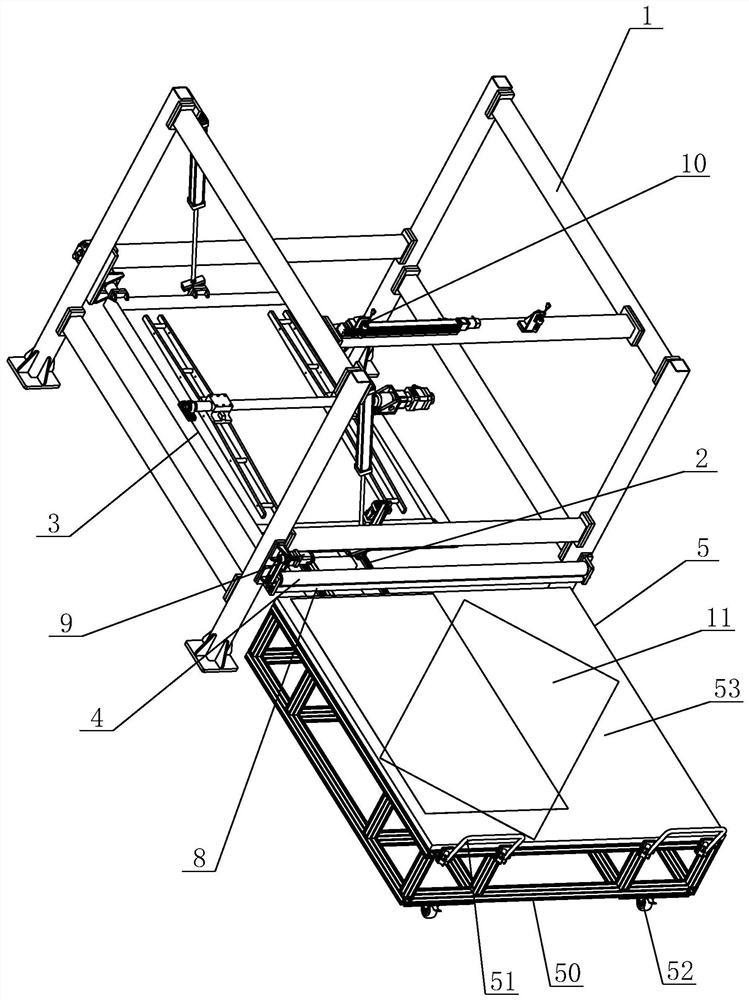
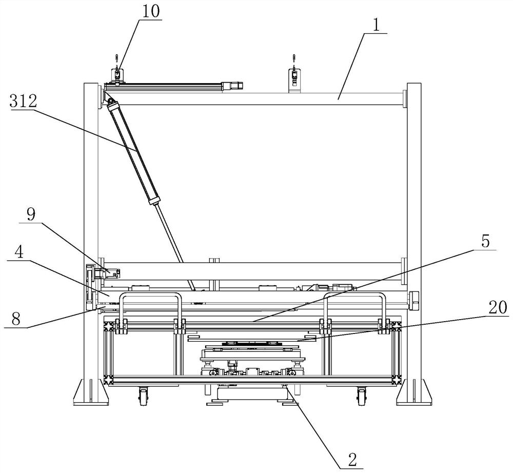
[0036] See Figure 1 to 9 As shown in the present embodiment, a large-sized liquid crystal screen polarizing sheet tear paste integrated machine includes a body frame 1, a liquid crystal screen transplanting mechanism 2, a polarizer bonding mechanism 3, a tear film roller 4, and an upper and lower bodies 5, One side of the main body frame 1 is used as the inlet and export side of the liquid crystal screen 11, and the other side adjacent to the entry and exit side is suck the side, and the upper and lower bodies 5 include frame 50, handrail 51, travel wheel 52 and table The panel 53, one side of the frame 50 is disposed, and the bottom ferrous portion of the frame 50 is attached, and the top of the frame 50 is provided for placing the table panel 53 of the liquid crystal screen 11 to be restarted.
[0037]The liquid crystal screen transfer mechanism 2 is used to drive the upper and lower bodder 5 lifting, the position correction when the bottom portion of the main body frame 1 is applied, including the transplanting platform 20, the transverse shift module 21, the lifting module 22 The longitudinal movement module 23 and the rotation module 24, the transverse shift module 21 includes a bottom support frame 210 that extends into the bottom of the main body frame 1, two transverse transverse line rails 211, drive racks 212, and transverse drive motor 213, two The root transverted line guide 211 and the drive rack 212 are fixed to the bottom support frame 210 in the longitudinal direction, and the transverse connection plate 214 is mounted on the transmitted linear guide 211 by the slider, and the output shaft of the drive motor 213 is mounted on the output shaft of the drive motor 213. The drive gear 215 is engaged with the drive rack 212, the lifting module 22 includes four lifting seat 220 and lift drive motor 221, four lift seats 220 are mounted on the traversal connecting plate 214, and four lifting seat 220 lifting The axis is connected to the bottom of the lifting plate 222, and the lifting drive motor 221 drives four lifting seats 220 by the transmission shaft, the worm gear and the worm, and the raised shaft synchronization of the four lifting seat 220, the longitudinal moving module 23 includes a longitudinal drive motor 230 The two longitudinal linear guides 231 and the ball screw parallel spacer 231 are fixed to the lifting connecting plate 222 along the longitudinal parallel intervals, and the longitudinal connecting plate 233 is fitted to the two longitudinal linear guide 231 by the slider. The longitudinal drive motor 230 is connected to the ball screw panel sheet 232, and the nut of the ball screw panel sheet 233 is connected to the longitudinal connecting plate 233, the rotation module 24 includes a rotary drive motor 240, a curved rail 241, and a rotary transmission assembly 242, an arc guide rail. 241 is mounted on the longitudinal connecting plate 233, and the transmissive platform 20 is mounted on the curved rail 233 by a slider, and the rotary drive motor 240 drives the transplanting platform 20 by the rotary transmission assembly 242 to rotate along the arc-shaped guide rail 241.
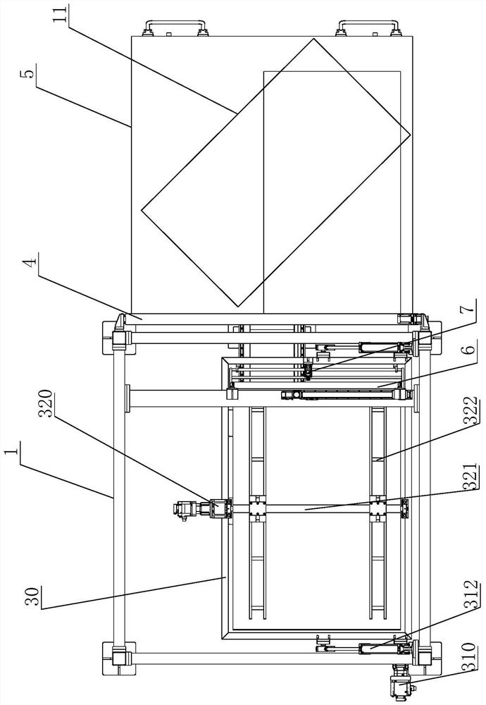
[0038] The polarizer bonding mechanism 3 is used to automatically bond the polarizer to the liquid crystal screen after manual material, which includes flip frame 30, the first flip drive assembly 31, the second flip drive assembly 32, and the polarizing plate 33, The flip frame 30 is provided in the main body frame 1 and is hinged on the main body frame 1, and the first flipping drive assembly 31 drives the flip frame 30 in the direction of the body frame 1 in the direction of adsorbed side toward the side of the polarizer. Since then, the first flip drive assembly 31 includes a first flip motor 310, and both ends of the hinged side of the flip frame 30 extend outwardly, the rotating shaft 311 is provided, and the mating shaft is provided with a rotary housing, the first flip motor. The output shaft of 310 is connected to one of the rotating shaft 311 in which the drive member is connected, and the middle of the top of the top of the main body frame 1 is hinged to the middle of the two sides of the hinge sides of the flip frame 30, and the second flip drive assembly is hinged. The 32 driving polarizing plate 33 is flip 180 ° in the flip frame 30, and the second flip drive assembly 32 includes a second flip motor 320 and a flip shaft 321, and one end of the flip shaft 321 is rotatably mounted to the flip frame 30. On the side of the hinge side, the other end is rotatably mounted on the opposite side of the hinged side by the bearing housing, and two mounting frames 322 are fixed, and the polarizer strip 33 is fitted to the mounting frame 322. The output shaft of the second flip motor 320 is rotated by the drive member drives the flip shaft 321.
[0039] One end of the inverting frame 30 is adjacent to the on-front side is provided with a press roller 6 on the liquid crystal screen on the liquid crystal screen, and the pressing roller 6 is connected to the pressing roller 7, the tear film roller 4 is connected to the pressing roller 7. The input and exit side of the main body frame 1 can be rotatably fitted, the tear film drive assembly drives the tear film roller 4 rotation, and the lower side of the tear film roller 4 can be rotatably provided with a support roller 8 for supporting the liquid crystal screen to prevent the liquid crystal screen from being stressed. Excessive damage, the tear film drive assembly includes a tear film drive motor 9, and the tear film drive motor 9 is rotated by the transmission assembly of the synchronous belt and the synchronous wheel assembly.
[0040] The top of the main frame 1 is mounted with a visual detecting device 10 for detecting the relative position of the polarizer and the liquid crystal screen. The visual detecting device 10 communicates with the liquid crystal screen transplanting mechanism 2, and the liquid crystal screen transplanting mechanism 2 passes through the visual detecting device 10. To correct the position of the polarizer and the LCD screen.
[0041] The LCD on the LCD screen 11 needs to be tearned when he is heavy, then the new polarizer is re-sticked. The specific operation is as follows:
[0042] When tearing film: Artificial will need to tear the liquid crystal screen of the tear of the polarizer to be placed in the designated position of the upper and lower bodies 5 (generally 45 °, convenient to tear the polarizer), push the upper and lower binding bus 5 to the upper position The lifting module 22 rises to a height through a transplanting platform 20 to a height, and the transmissive stage group 21 drives the transmissive platform 20 to move to the tear film position near the main body frame 1. Artificiality The outer polarizer is torn open, attached to the tear film roller 4. The starting device, the transmissive module 21 drives the transplanting platform 20 to move in the direction away from the main body frame 1, and the tear film drive motor 9 drives the tear film roller 4 to rotate the film, the support roller 8 supports the liquid crystal screen to prevent excessive force. damage. The transverse shift module 21 drives the upper and lower bodies 5 to move to the outside of the main body frame 1, and then the lifting module 22 is lowered, and the tear film is completed.
[0043] When the polarizer is fitted: start the device, the polarizing plate strip 33 rotates by the first flip drive assembly 31 and the second flip drive assembly 32, so that the polarizing plate strip 33 is close to the vertical state (70 ° -90 °), and The adsorption surface of the polarizer suction plate 33 is turned to the outside and facing the work person. Manually placing the polarizer in the specified position and adsorbed, tearing the polarizer protective film and inspects. After the completion, the polarizing plate strip 33 rotates by the first flip drive assembly 31 and the second flip drive assembly 32, and the polarizing plate strip 33 is flipped to the horizontal state, and the polarizing plate strip 33 adsorbs the surface to the lower side. The polarizer faces the ground. Artificial will need to be placed in the designated position of the liquid crystal screen of the polarizer 5, push the upper and lower bodies 5 to the upper position, and the lifting module 22 will rise by the transplanting platform 20 To a certain height, the transverse shift module 21 drives the transplanting platform 20 to move to the bonding position in a direction close to the main body frame 1. The visual detecting device 10 determines the relative position of the polarizer and the liquid crystal screen, and the liquid crystal screen transplanting mechanism 2 correction is performed according to the visual position. After the correction is completed, the press-driven cylinder 7 drives the press roller 6 down pressure (pressure adjustable), the transverse shift module 21 drives the upper and lower bonded trolley 5 to move to the outside of the body frame 1, and then the lifting module 22 drops down, completed .
[0044] Note that the above is only preferred embodiments of the present invention and the principles of technology applied. Those skilled in the art will appreciate that the invention is not limited to the particular embodiments described herein, and various significant changes, reinterping, and alternatives to those skilled in the art without departing from the scope of the invention. Therefore, although the present invention has been described in detail by the above, the present invention is not limited to the above embodiments, and more other equivalent embodiments may be included not only without departing from the inventive concept. The scope is determined by the appended claims.

PUM

no PUM

Description & Claims & Application Information

We can also present the details of the Description, Claims and Application information to help users get a comprehensive understanding of the technical details of the patent, such as background art, summary of invention, brief description of drawings, description of embodiments, and other original content. On the other hand, users can also determine the specific scope of protection of the technology through the list of claims; as well as understand the changes in the life cycle of the technology with the presentation of the patent timeline. Login to view more.

Similar technology patents

Roller washing machine front cover and roller washing machine

InactiveCN105671866Aeasy to usesave space
Owner:QINGDAO HAIER DRUM WASHING MACHINE

System for network-loading game data and its method

InactiveCN1744096Asave spacePrevent Pirated Software
Owner:INVENTEC CORP

Packaging method of flat rolled toilet paper

ActiveCN104129542Asave space
Owner:上海松川峰冠包装自动化有限公司

Pixel structure of liquid-crystal display device and liquid-crystal display device

PendingCN106842748Asave spaceIncrease the storage capacitor area
Owner:TRULY SEMICON

Classification and recommendation of technical efficacy words

  • save space
  • Reduce equipment costs

Multi-node management method and system

Owner:XFUSION DIGITAL TECH CO LTD

Chemiluminescence immunoassay device

InactiveCN104777321Asave spaceHigh detection throughput
Owner:TSINGHUA UNIV +1

Protective frame for mobile communication device

InactiveUS20130088815A1minimize size and weightsave space
Owner:TAER INNOVATION

Folding type aerial photography aircraft

InactiveCN105035303Areduce volumesave space
Owner:WUXI MIRACLE SCI & TECH CO LTD

Method and device for producing high-purity natural graphite

Owner:HEILONGJIANG UNIVERSITY OF SCIENCE AND TECHNOLOGY

Gesture recognition method based on recurrent 3D convolutional neural network

InactiveCN107590432AReduce equipment costsConvenient non-contact gesture recognition
Owner:BEIJING UNION UNIVERSITY
Why Eureka
Try Eureka