Medical clinical obstetrics and gynecology drainage tube angle adjusting device
An angle adjustment device and drainage tube technology, applied in the direction of catheters, suction devices, and other medical devices, can solve the problems of folding the drainage tube in half, affecting the drainage effect, and limiting the length of the hollow rod of the drainage tube, so as to achieve convenient use and guarantee The effect of patency and easy operation
- Summary
- Abstract
- Description
- Claims
- Application Information
AI Technical Summary
Problems solved by technology
Method used
Image
Examples
Embodiment 1
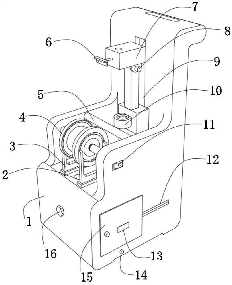
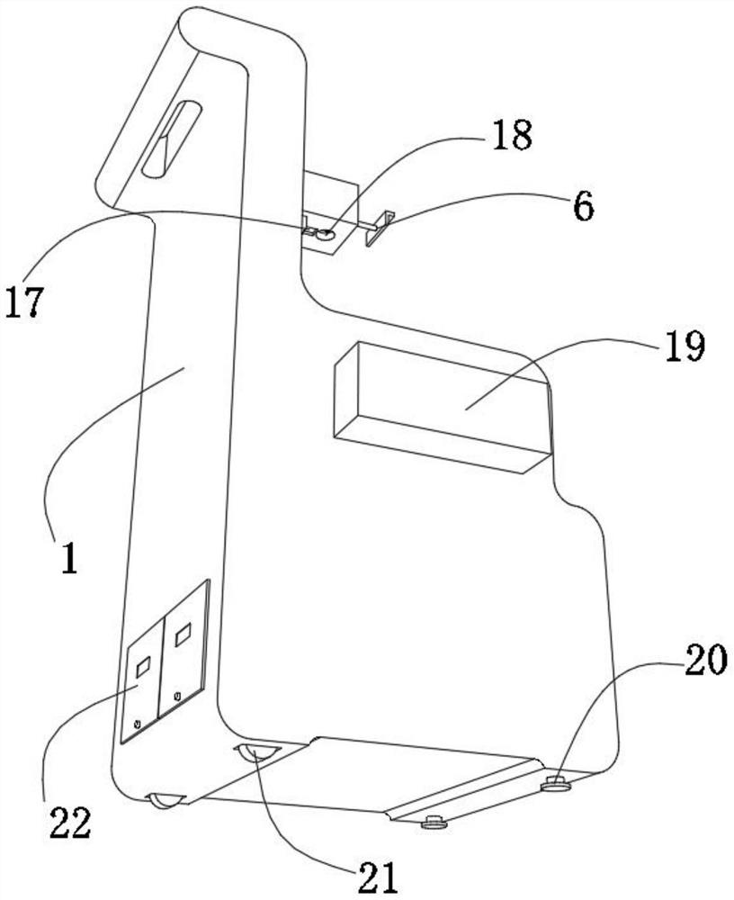
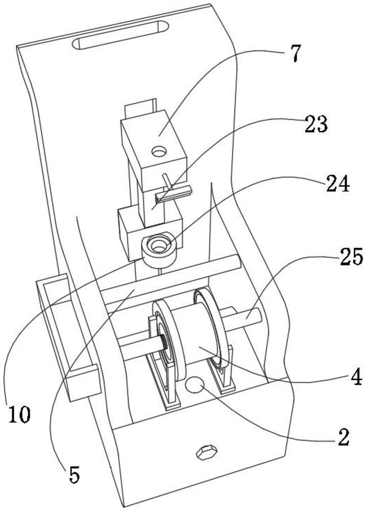
[0033] A medical clinical obstetrics and gynecology drainage tube angle adjustment device, such as Figure 1-5As shown, it includes a body 1, the top outer wall of the body 1 is provided with a through hole 1; the bottom inner wall of the body 1 is provided with a placement cavity, and the inner wall of the placement cavity is provided with an automatic winding structure, and the automatic winding structure includes an inclined Shaped adjustment column 27, several rubber plates 26 and handle 16, one end of the adjustment column 27 is rotatably connected to the inner wall of one side of the cavity; On the peripheral outer wall; one end of the handle 16 is rotatably connected to one side of the outer wall of the body 1, and one end of the handle 16 is connected with an end of the adjustment post 27 through a connecting shaft; It can be wound around the adjustment column 27 once and then drawn out from the through hole 12. When it is necessary to drag the drainage tube to adjust ...
Embodiment 2
[0044] A medical clinical obstetrics and gynecology drainage tube angle adjustment device, such as figure 1 , image 3 and Figure 6 As shown, in order to adjust the use orientation of the I-shaped column 4; this embodiment makes the following improvements on the basis of Embodiment 1: the outer walls of the opposite side of the body 1 are fixed with bolts that match the outer walls of the I-shaped column 4. Connecting column 25, one end of connecting column 25 is welded with magnet 34, and the two ends of I-shaped column 4 are all fixed with iron block 37 by bolt. Squeeze the I-shaped column 4 in the middle to deform its width, so that the iron block 37 on the I-shaped column 4 is separated from the magnet 34 on the connecting column 25, so that the I-shaped column 4 can be easily and flexibly removed, and the I-shaped column can be adjusted according to the actual clinical situation. The use position of the column 4 has a simple structure.
[0045] When this embodiment is...
PUM
 Abstract
Description
Claims
Application Information
 - R&D
- Intellectual Property
- Life Sciences
- Materials
- Tech Scout
- Unparalleled Data Quality
- Higher Quality Content
- 60% Fewer Hallucinations
Browse by: Latest US Patents, China's latest patents, Technical Efficacy Thesaurus, Application Domain, Technology Topic, Popular Technical Reports.
© 2025 PatSnap. All rights reserved.Legal|Privacy policy|Modern Slavery Act Transparency Statement|Sitemap|About US| Contact US: help@patsnap.com


