Arrangement structure for limiting TBM (Tunnel Boring Machine) in-hole starting site due to reservoir flood overflow channel

A technology for arranging structures and spillways, applied in infrastructure engineering, water conservancy engineering, sea area engineering, etc., can solve problems such as unfavorable TBM starting construction, starting site restrictions, affecting reservoir drainage, etc., and achieves easy operation and implementation and strong stability , economical and reasonable effect

Pending Publication Date: 2022-02-25
FUJIAN UNIV OF TECH +2
View PDF2 Cites 0 Cited by
  • Summary
  • Abstract
  • Description
  • Claims
  • Application Information

AI Technical Summary

Problems solved by technology

[0002] The spillway is the flood control equipment for water conservancy structures such as reservoirs. It is mostly built on one side of the dam. When the water level in the reservoir exceeds the safety limit, the water will flow downstream from the spillway to prevent the dam from being destroyed. , will affect the drainage of the reservoir. At the same time, the spillway and the surrounding high and steep slopes are no

Method used


Image

  • Arrangement structure for limiting TBM (Tunnel Boring Machine) in-hole starting site due to reservoir flood overflow channel
  • Arrangement structure for limiting TBM (Tunnel Boring Machine) in-hole starting site due to reservoir flood overflow channel
  • Arrangement structure for limiting TBM (Tunnel Boring Machine) in-hole starting site due to reservoir flood overflow channel

Examples


Embodiment Construction

[0021] Below by embodiment and in conjunction with accompanying drawing, the present invention will be further described:

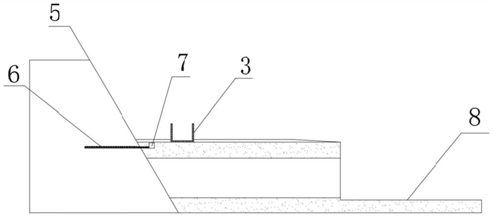
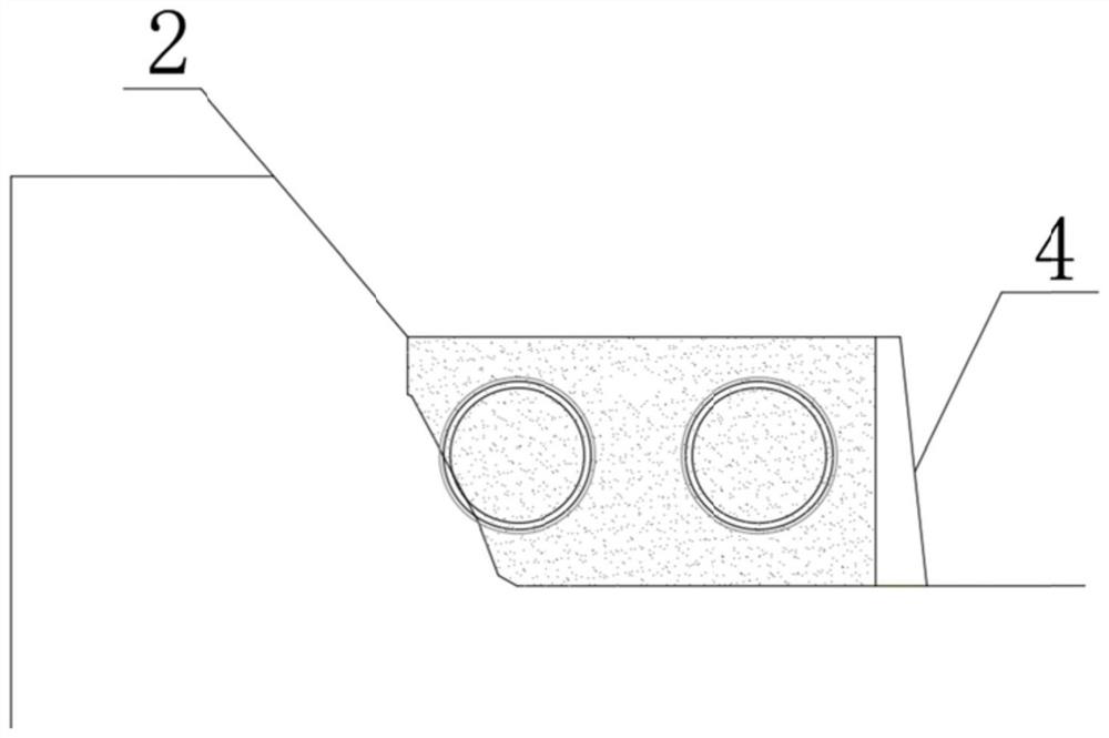
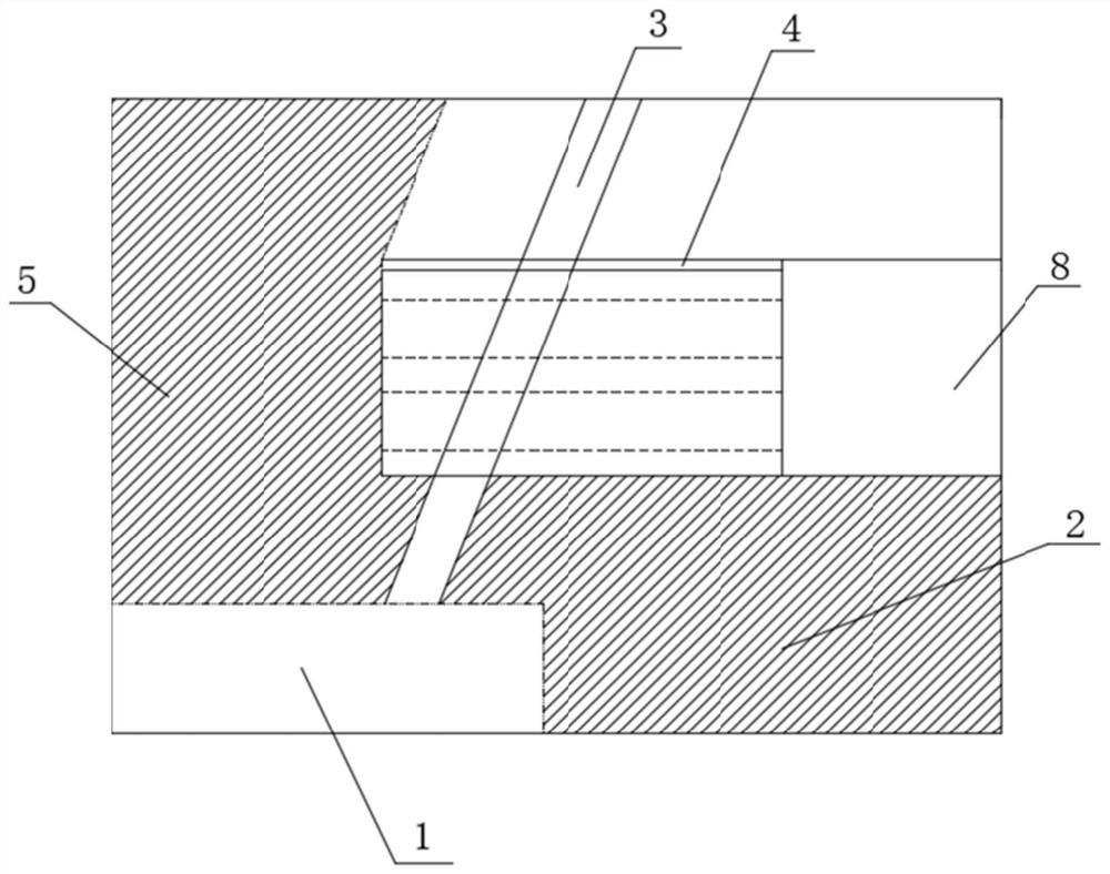
[0022] Such as figure 1 — image 3 As shown in Fig. 1, a layout structure where the TBM entry site is limited due to the reservoir spillway, a reservoir 1 has been arranged on the side of the entrance of the tunnel to be excavated, and the side of the reservoir 1 close to the tunnel to be excavated has a second The side slope 2 has a second side slope 5 at the entrance of the tunnel to be excavated, and the reservoir spillway 3 is obliquely intersected with the extension direction of the tunnel to be excavated, so that the site between the reservoir spillway 3 and the tunnel to be excavated Due to the limitation, it is impossible to initiate TBM entry, including building a retaining wall 4 on the side away from the first slope 2 outside the entrance of the tunnel, and the front end of the retaining wall 4 is connected with the second slope 5 of the tunne...


PUM

PropertyMeasurementUnit
Thicknessaaaaaaaaaa
Sectional areaaaaaaaaaaa
Lengthaaaaaaaaaa

Abstract

The invention discloses an arrangement structure for limiting a TBM (Tunnel Boring Machine) in-hole starting site due to a reservoir flood overflow channel, which is characterized in that a retaining wall is built on one side, far away from a first side slope, outside a tunnel inlet hole, a front end of the retaining wall is connected with a second side slope of a to-be-excavated tunnel, and concrete is poured in an area defined by the retaining wall, the first side slope and the second side slope; meanwhile, a plurality of arc-shaped long pipe sheds arranged at intervals are inserted into the junction of the plain concrete and the second slope for reinforcement, rear ends of the long pipe sheds extend into the plain concrete, rear ends of all the long pipe sheds are connected with the same guide beam, and the guide beam is arc-shaped, is matched with the top outline of a hole formed by TBM tunneling and is located above the hole formed by TBM tunneling; a TBM starting platform is located behind the backfill plain concrete, and a reservoir spillway is located above the backfill plain concrete. The construction method is clear in thought, economical, reasonable, safe, reliable, easy to operate and implement, good in construction quality and small in disturbance to the surrounding environment.

Description

technical field [0001] The invention relates to a TBM starting layout structure technology, in particular to a layout structure for solving the limitation of the starting site of a TBM entry hole caused by a reservoir overflow channel. Background technique [0002] The spillway is the flood control equipment for water conservancy structures such as reservoirs. It is mostly built on one side of the dam. When the water level in the reservoir exceeds the safety limit, the water will flow downstream from the spillway to prevent the dam from being destroyed. , will affect the drainage of the reservoir. At the same time, the spillway and the surrounding high and steep slopes are not conducive to the initial construction of TBM. The conventional TBM initial construction method uses equipment or facilities such as reaction frames and temporarily assembled negative ring segments in the initial working well. Push the shield on the starting base into the reinforced soil. At this time, ...

Claims


Application Information

Patent Timeline
IPC IPC(8): E02B3/12E02B8/06E02B3/06E02D15/02
CPCE02B3/12E02B8/06E02B3/066E02D15/02E02B3/128Y02A10/11
Inventor 詹金武黄明王双龙华东杜广召刘毓川刘铮李威振李应娇夏国松廖帅
Owner FUJIAN UNIV OF TECH
Why Eureka
Try Eureka