Concrete conveying pipe manufacturing method, concrete conveying pipe and pumping equipment

A technology for a concrete conveying pipe and a manufacturing method, which is applied in the field of conveying pipes, can solve the problems of reducing cracking damage of conveying pipes, damage of conveying pipes, cracking of inner pipes, etc., and achieves the effects of reducing cracking risk, reducing pipe bursting, and improving pressure bearing capacity.

Pending Publication Date: 2022-02-25
SANY AUTOMOBILE MFG CO LTD
View PDF0 Cites 0 Cited by
  • Summary
  • Abstract
  • Description
  • Claims
  • Application Information

AI Technical Summary

Problems solved by technology

[0004] The invention provides a method for manufacturing a concrete conveying pipe, a concrete conveying pipe and pumping equipment, which are used to solve the problem that the inner pipe of the double-layer composite conveying pipe is impacted by concrete in the prior art, which may easily cause the inner pipe to crack and fall off, resulting in damage to the conveying pipe problems, reducing the risk of cracking damage to the delivery pipe

Method used


Image

  • Concrete conveying pipe manufacturing method, concrete conveying pipe and pumping equipment
  • Concrete conveying pipe manufacturing method, concrete conveying pipe and pumping equipment
  • Concrete conveying pipe manufacturing method, concrete conveying pipe and pumping equipment

Examples


Embodiment Construction

[0032] In order to make the purpose, technical solutions and advantages of the present invention clearer, the technical solutions in the present invention will be clearly and completely described below in conjunction with the accompanying drawings in the present invention. Obviously, the described embodiments are part of the embodiments of the present invention , but not all examples. Based on the embodiments of the present invention, all other embodiments obtained by persons of ordinary skill in the art without creative efforts fall within the protection scope of the present invention.

[0033] Combine below Figure 1 to Figure 10 The manufacturing method of the concrete delivery pipe, the concrete delivery pipe and the pumping equipment of the present invention will be described.

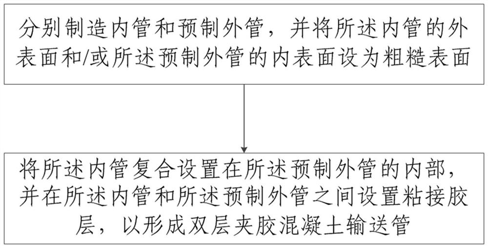
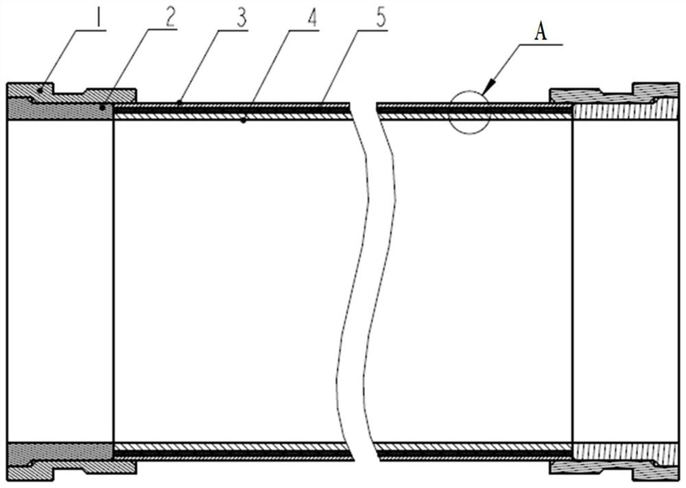
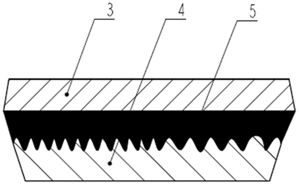
[0034] refer to figure 1 , the present embodiment provides a method for manufacturing a concrete delivery pipe, the manufacturing method comprising: respectively manufacturing the inner pipe 4 a...


PUM

PropertyMeasurementUnit
diameteraaaaaaaaaa
surface roughnessaaaaaaaaaa
thicknessaaaaaaaaaa

Abstract

The invention provides a concrete conveying pipe manufacturing method, a concrete conveying pipe and pumping equipment. The concrete conveying pipe manufacturing method comprises the steps that an inner pipe and a prefabricated outer pipe are manufactured respectively, and the outer surface of the inner pipe and/or the inner surface of the prefabricated outer pipe are/is set to be rough surfaces; and the inner pipe is arranged in the prefabricated outer pipe in a composite mode, and a bonding glue layer is arranged between the inner pipe and the prefabricated outer pipe, so that the double-layer laminated concrete conveying pipe is formed. According to the concrete conveying pipe manufacturing method, the concrete conveying pipe and the pumping equipment, the bonding glue layer is arranged between the inner pipe and the outer pipe, and the rough surface is arranged to be connected with the bonding glue layer, so that firm compounding of the inner pipe and the outer pipe can be achieved, the phenomenon of chipping of the inner pipe can be avoided, the phenomena of pipe explosion and pipe blocking of the conveying pipe are reduced, the overall pressure bearing capacity of the conveying pipe is improved, and the cracking risk of the inner pipe is greatly reduced; and the conveying pipe is simple in structure, simple and convenient in production process, easy to implement, low in cost and suitable for mass production.

Description

technical field [0001] The invention relates to the technical field of conveying pipes, in particular to a method for manufacturing a concrete conveying pipe, a concrete conveying pipe and pumping equipment. Background technique [0002] At present, with the popularization of mechanized construction of various engineering constructions such as urban construction, roads and bridges, concrete pumping devices such as towed concrete pumps and concrete pump trucks for concrete transportation have gradually become important equipment for concrete mechanized construction. Among them, the concrete delivery pipe is a key component that affects the service life and stability of concrete pumping equipment. In order to slow down the wear of the conveyed concrete coarse-grained material on the inner wall of the pipe, the inner wall of the concrete conveying pipe needs to have high hardness and wear resistance; at the same time, in order to prevent the pipe from being subjected to externa...

Claims


Application Information

Patent Timeline
Patent Type & Authority Applications(China)
IPC IPC(8): F16L9/14F16L43/00F16L57/02F16B11/00B22D13/02
CPCF16L9/14F16L43/00F16L57/02F16B11/008B22D13/02
Inventor 赵杰贡太敏余泉旭
Owner SANY AUTOMOBILE MFG CO LTD
Why Eureka
Try Eureka