Chemical catalytic furnace with high sealing performance

A chemical catalysis and sealing technology, applied in the field of catalytic furnaces, can solve the problems of adding different types of catalysts, unable to continue to add catalysts, etc., and achieve the effect of improving the catalytic effect and improving the catalytic efficiency.

Active Publication Date: 2022-02-25
HUAIYIN TEACHERS COLLEGE
View PDF8 Cites 0 Cited by
  • Summary
  • Abstract
  • Description
  • Claims
  • Application Information

AI Technical Summary

Problems solved by technology

[0005] However, in the catalysis process of the existing catalytic furnace, it can only catalyze a certain amount of waste at one time, and cannot continue to add catalysts during the catalysis process, and cannot continuously add different types of catalysts according to the degree of catalysis of the exhaust gas. , we propose a highly airtight chemical catalytic furnace

Method used


Image

  • Chemical catalytic furnace with high sealing performance
  • Chemical catalytic furnace with high sealing performance
  • Chemical catalytic furnace with high sealing performance

Examples


Embodiment 1

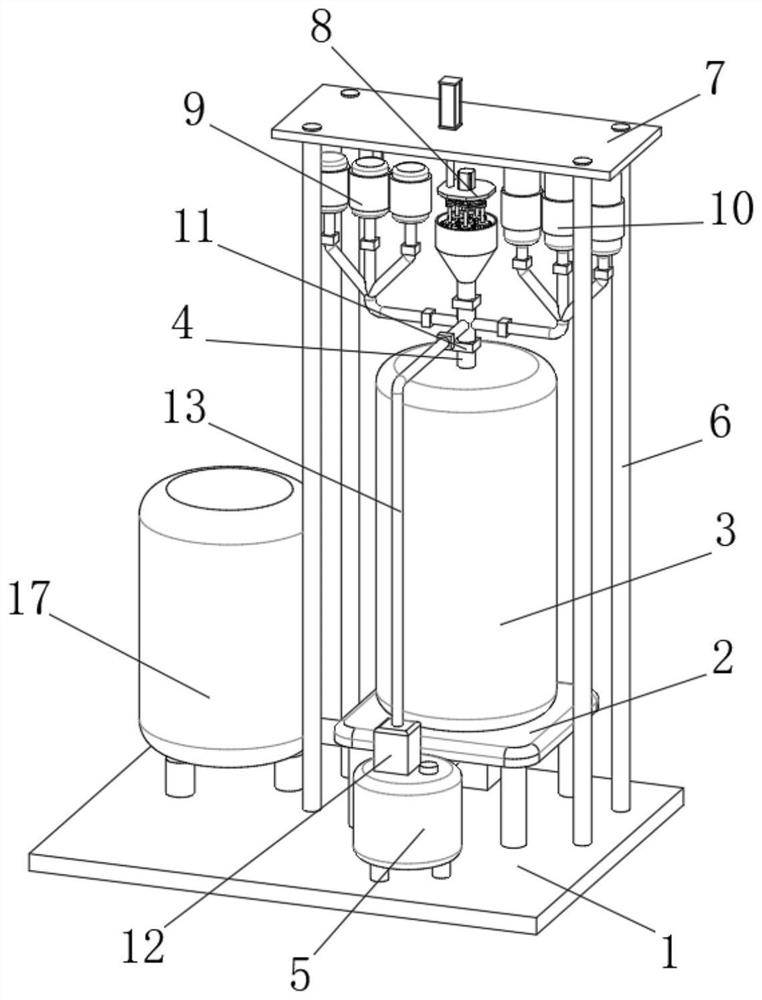
[0032] see Figure 1-8 , the present invention provides a technical solution:

[0033] A chemical catalytic furnace with high airtightness. When the device is in use, solid, liquid or gaseous catalysts are respectively added into the catalytic tube 4 through the solid catalyst adding mechanism 8, the liquid catalyst adding mechanism 9 or the gaseous catalyst adding mechanism 10, and catalyzed The tube 4 is installed in the catalytic furnace 3, and the catalytic furnace 3 is fixedly connected to the surface of the base 1 through the installation platform 2, so that the catalytic furnace 3 can be fixed and operated in a safe and stable environment, and the bottom surface of the installation platform 2 is fixedly connected with The heating furnace 14, the heating furnace 14 is connected with the fuel tank 17 installed on the base 1 through the fuel pipe 16, the heating furnace 14 can be operated for a long time through the fuel tank 17, and the continuous operation of the heating...

Embodiment 2

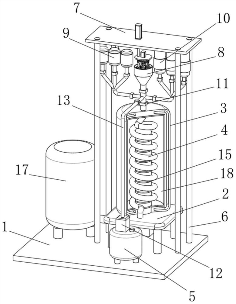
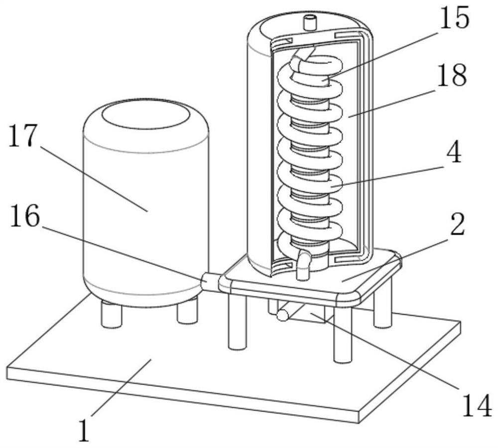
[0038] see Figure 1-8, on the basis of Embodiment 1, the present invention provides a technical solution:

[0039] A chemical catalytic furnace with high sealing performance. A pump body 12 is installed inside the waste gas barrel 5. A return pipe 13 is hollowly connected above the pump body 12, and the return pipe 13 is hollowly connected with the upper part of the catalytic pipe 4. The return pipe 13 The connection with the catalytic tube 4 is located above the electromagnetic valve 6 11, and the inside of the return tube 13 is equipped with a heating furnace 14, so that the solid catalyst adding mechanism 8, the liquid catalyst adding mechanism 9, and the gaseous catalyst adding mechanism 10 flow into the catalytic tube 4. After the catalyst is added for one catalysis, the exhaust gas may not be fully catalyzed. When the heating furnace 14 is turned on, the exhaust gas is pumped from the return pipe 13 into the exhaust gas barrel 5 again through the pump body 12, and refil...

Embodiment 3

[0042] see Figure 1-8 , on the basis of Embodiment 2, the present invention provides a technical solution:

[0043] A chemical catalytic furnace with high airtightness, solid catalyst adding mechanism 8, liquid catalyst adding mechanism 9 and gaseous catalyst adding mechanism 10 are all installed on the mounting plate 7 installed above the fixedly connected mounting frame 6 on the base 1, solid catalyst adding Mechanism 8 comprises the hydraulic cylinder 81 that is installed on the mounting plate 7 and the inlet 812 that is installed on the catalytic tube 4, can add solid chemical position in the catalytic tube 4 through the inlet 812, and the upper installation of hydraulic cylinder 81 There is a telescopic rod 82, and the bottom end of the telescopic rod 82 runs through the mounting plate 7 and is fixedly connected with a lifting platform 83. The hydraulic cylinder 81 drives the telescopic rod 82 to slide up and down connected to the lifting platform 83, so that the lifting...


PUM


Abstract

The invention provides a chemical catalytic furnace with high sealing performance in the technical field of catalytic furnaces. The chemical catalytic furnace comprises a base, a mounting table, a catalytic furnace body, catalytic pipes, a pump body, a heating furnace, a heating pipe and a fuel tank, the mounting table is mounted on the surface of the base, the catalytic furnace body is fixedly connected to the surface of the mounting table, and the catalytic pipes are mounted in the catalytic furnace body. The catalytic furnace of the device adopts an integrated structure, and meanwhile, the catalytic pipe is arranged to be spiral. Waste gas can continue to be fully catalyzed in the catalytic furnace.The catalytic pipes are communicated end to end, so that the waste gas can be continuously and circularly catalyzed for multiple times, and the catalytic efficiency is improved. According to the device, different solid-state, gas-state or liquid-state catalysts can be continuously added in the catalytic process of waste gas in the catalytic pipes, so that the waste gas in the catalytic pipes can be continuously catalyzed; and solid, gaseous or liquid catalyst mixtures with different dosage ratios can be added according to the catalytic degree of the waste gas, so that the catalytic effect is improved.

Description

technical field [0001] The invention relates to the technical field of catalytic furnaces, in particular to a chemical catalytic furnace with high sealing performance. Background technique [0002] Catalytic incinerator is also called catalytic combustion incinerator and catalyst incinerator. The catalytic incineration method, until now, has almost all used the oxidative combustion method to treat the three wastes, so that the harmful waste is oxidized and decomposed into CO2 and H2O at a temperature above 900 ° C, thereby purifying the exhaust gas. [0003] After retrieval, Chinese Patent No. CN202021805171.9 discloses a new type of high-efficiency integrated catalytic furnace, including a furnace body, a base at the bottom of the furnace body, a first gas guide cover at one end of the furnace body and a device. The second air guide cover at the other end of the furnace body, the first air guide cover is provided with an air intake pipe at one end, the furnace body is prov...

Claims


Application Information

Patent Timeline
Patent Type & Authority Applications(China)
IPC IPC(8): F23G7/07
CPCF23G7/07
Inventor 闫成蕾邓庆明
Owner HUAIYIN TEACHERS COLLEGE
Why Eureka
Try Eureka