

Water-saving cooling tower for mixed aromatic hydrocarbon production
A technology of mixed aromatics and cooling towers, which is applied in the direction of water shower coolers, direct contact heat exchangers, heat exchanger types, etc., can solve the problem of inability to guarantee the cooling effect of cooling towers, increase the water consumption of cooling towers, and unfavorable water Resource recycling and other issues, to achieve a good water-saving effect, increase the specific surface area of heat dissipation, and reduce the effect of hollow phenomenon
- Summary
- Abstract
- Description
- Claims
- Application Information
AI Technical Summary
Problems solved by technology
Method used
Image

Examples
Embodiment Construction
[0032] The present invention will be described in detail below, and the technical solutions in the embodiments of the present invention will be clearly and completely described. Apparently, the described embodiments are only some of the embodiments of the present invention, not all of them. Based on the embodiments of the present invention, all other embodiments obtained by persons of ordinary skill in the art without making creative efforts belong to the protection scope of the present invention.
[0033] The present invention provides a kind of water-saving cooling tower for the production of mixed aromatics through improvement, and the technical scheme of the present invention is:
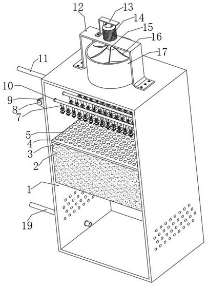
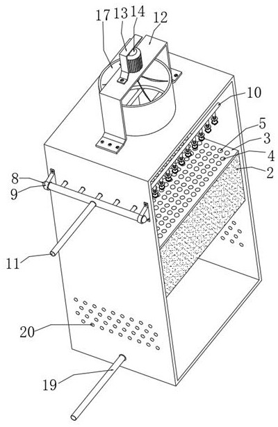
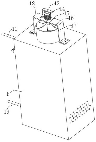
[0034] Such as Figure 1 to Figure 8 As shown, the embodiment of the present invention provides a water-saving cooling tower for the production of mixed aromatics, comprising a shell 1, the outer walls of both sides of the shell 1 are distributed and fixedly connected with fixed seats 9, and the...
PUM
 Abstract
Description
Claims
Application Information