Eureka AIR delivers breakthrough ideas for toughest innovation challenges, trusted by R&D personnel around the world.

Structure of dust collector

A technology for vacuum cleaners and dust cups, which is applied to machine parts, robot cleaners, electromechanical devices, etc. It can solve the problems of inconvenient wiring of vacuum cleaners, and achieve the effects of benefiting human health, prolonging the service life, and facilitating wiring

Active Publication Date: 2022-03-01
NINGBO DECHANG ELECTRICAL MACHINERY MFG CO LTD
View PDF8 Cites 0 Cited by
  • Summary
  • Abstract
  • Description
  • Claims
  • Application Information

AI Technical Summary

Problems solved by technology

[0004] The present invention is to overcome the disadvantage of inconvenient wiring of the vacuum cleaner in the prior art, and provides a structure of the vacuum cleaner which is convenient for wiring

Method used


Image

  • Structure of dust collector
  • Structure of dust collector
  • Structure of dust collector

Examples


Embodiment Construction

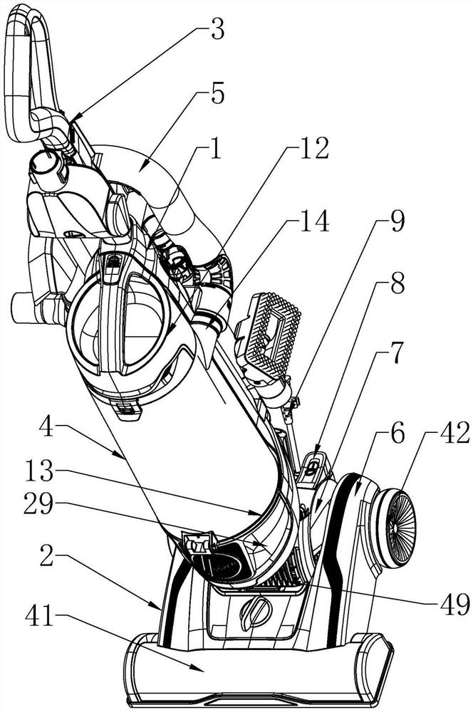
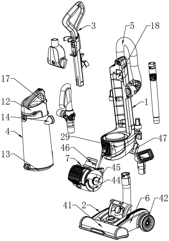
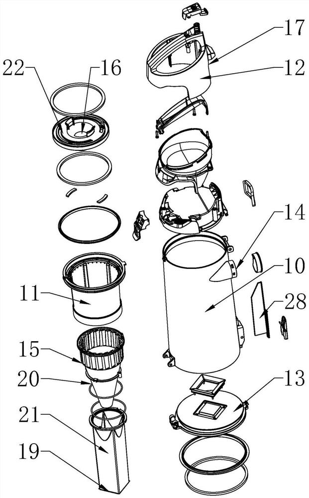
[0032] The present invention will be further described below in conjunction with the accompanying drawings and specific embodiments.

[0033] Such as figure 1 In the described embodiment, a structure of a vacuum cleaner includes a body 1, a mop 2 is detachably connected to the bottom of the body 1, a handle 3 is connected to the top of the body 1, and a dust cup is provided on the body 1 Assembly 4 and hose 5, dust cup assembly 4 and hose 5 are detachably connected to body 1, floor mop 2 communicates with dust cup assembly 4 through hose 5, floor mop 2 includes bracket 6, roller brush and The motor assembly 7, the roller brush and the motor assembly 7 are all detachably connected to the bracket 6, the roller brush is connected to the bracket 6 under the drive of the motor assembly 7, and the motor assembly 7 is provided with a foot switch 8 and a power cord 9, Both the foot switch 8 and the power cord 9 are electrically connected with the motor assembly 7 .

[0034] Such as ...


PUM


Abstract

The invention discloses a structure of a dust collector, and aims to provide a structure of a dust collector convenient for wiring. The bottom of the machine body is detachably connected with a mop, the top of the machine body is connected with a handle, the machine body is provided with a dust cup assembly and a hose, the dust cup assembly and the hose are both detachably connected with the machine body, the mop is communicated with the dust cup assembly through the hose, the mop comprises a bracket, a rolling brush and a motor assembly, and the rolling brush and the motor assembly are both detachably connected with the bracket. The rolling brush is driven by the motor assembly to be rotationally connected with the bracket, a foot switch and a power line are arranged on the motor assembly, and the foot switch and the power line are both electrically connected with the motor assembly. The beneficial effects of the invention are that wiring is convenient; the use is convenient; heat dissipation of the motor body is facilitated, and the service life of the motor body is prolonged; dust in the dust cup body can be conveniently cleaned, meanwhile, the dust generation amount can be reduced, and human health is facilitated; the dust filtering and separating effect is good; and noise reduction is facilitated.

Description

technical field [0001] The present invention relates to the technical field related to vacuum cleaners, in particular to a structure of a vacuum cleaner. Background technique [0002] Vacuum cleaners can be divided into vertical, horizontal and portable according to their structure. The working principle of the vacuum cleaner is that under the action of the motor, the roller brush is driven to rotate and generate air negative pressure, which absorbs dust and collects it in the dust cup. [0003] When the vacuum cleaner is working, the mixed gas containing dust is sucked into the dust cup through the hose through the mop for separation, so that the dust stays in the dust cup, and the separated gas is used to dissipate heat from the motor and then discharged out of the body. The separated gas contains moisture. In order to extend the service life of the motor, it is often necessary to use a water absorption device to remove the moisture in the gas in the prior art. However, a...

Claims


Application Information

Patent Timeline
IPC IPC(8): A47L11/282A47L11/40H02K9/02
CPCA47L11/282A47L11/4041A47L11/4027A47L11/4013A47L11/40A47L11/4072H02K9/02A47L2201/00
Inventor 张罗欢
Owner NINGBO DECHANG ELECTRICAL MACHINERY MFG CO LTD
Why Eureka
Eureka Blog
Learn More