Auxiliary fixing device for joint trauma in orthopedics department
A joint trauma and fixation device technology, applied in non-surgical orthopedic operations, fractures, medical science, etc., can solve problems such as the inability to adjust the fixed position and fixed angle, and achieve the effect of avoiding dislocation movement and joint damage
- Summary
- Abstract
- Description
- Claims
- Application Information
AI Technical Summary
Problems solved by technology
Method used
Image
Examples
Embodiment 1
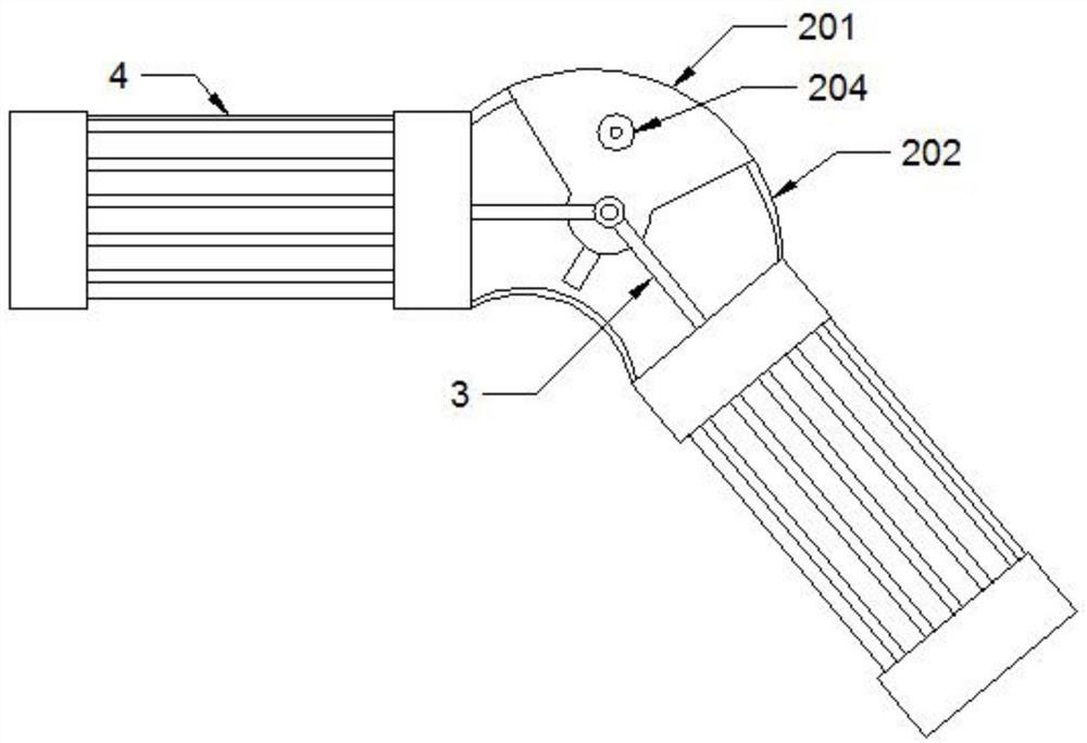
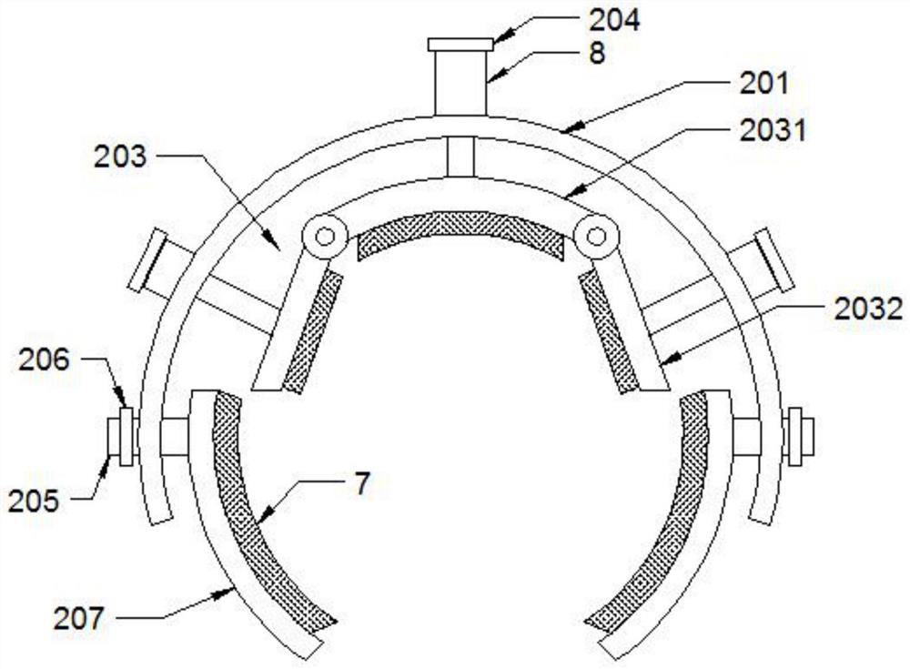
[0032] Such as Figure 1-2 As shown, an auxiliary fixation device for orthopedic joint trauma includes two annular sleeves; the bone joint fixation component is located between the two annular sleeves and includes a spherical mounting seat 201 for covering the bone joint, and the inside of the spherical mounting seat 201 Fixed plate 203 is provided, and fixed plate 203 comprises arc-shaped fixed plate 2031, and the two ends of arc-shaped fixed plate 2031 are respectively hinged with fixed plate 2032, and the spherical mounting base 201 is provided with three arc-shaped fixed plates 2031 and two respectively. The first fastening bolt 204 that is in conflict with the fixed plate 2032 is fixedly provided with three threaded sleeves 8 on the spherical mounting seat 201, and the three threaded sleeves 8 are respectively provided with an arc-shaped fixed plate 2031 and two fixed plates. 2032 interferes with the first set bolt 204 . The two ends of the spherical mount 201 are respec...
Embodiment 2
[0037] Such as Figure 1-2As shown, the two sides of the inside of the spherical mounting seat 201 are respectively provided with arc-shaped auxiliary support plates 207 below the two fixed flat plates 2032, and the two rotating shafts 205 respectively penetrate the spherical mounting seat 201 and extend to the inside of the spherical mounting seat 201 and the arc. Shaped auxiliary support plate 207 is fixedly connected. When the adjusting nuts 206 on the two rotating shafts 205 are tightened, the two arc-shaped auxiliary support plates 207 will fit tightly under the patient's bone joints. Then the respectively fixed arc-shaped fixing plate 2031, two fixed flat plates 2032, and two arc-shaped auxiliary support plates 207 can form a firm package on the peripheral circumference of the patient's bone joint, which is beneficial to further fix the patient's bone joint and avoid Misalignment of bone joints.
[0038] Moreover, the arc-shaped auxiliary support plate 207 located belo...
Embodiment 3
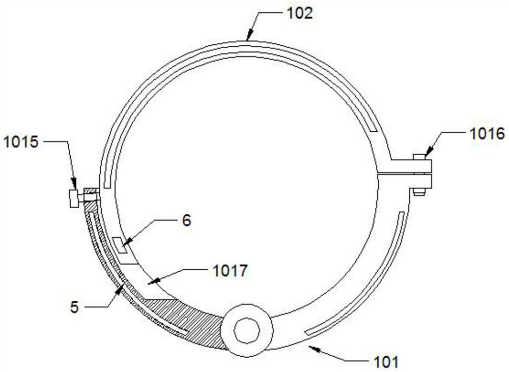
[0041] Such as Figure 1-4 As shown, the annular sleeve includes a lower arc sleeve 101 and an upper arc sleeve 102 .
[0042] The lower arc-shaped sleeve 101 includes two arc-shaped plates 1011, and a connecting shaft 1012 arranged between the two arc-shaped plates 1011. A torsion spring 1013 is sleeved on the connecting shaft 1011, and the two torsion shafts of the torsion spring 1013 are respectively connected with The two arc-shaped plates 1011 are fixedly connected, and the two arc-shaped plates 1011 are respectively rotatably connected to the connecting shaft 1012 through the connecting sleeve 1014, and one end of the upper arc-shaped sleeve 102 is slidably connected to the chute provided on one of the arc-shaped plates 1011 , and the arc-shaped plate 1011 is pierced with a second set bolt 1015 that conflicts with the upper arc-shaped sleeve 102, and the connecting ear provided at the other end of the upper arc-shaped sleeve 102 is set on the other arc-shaped plate 1011....
PUM
 Abstract
Description
Claims
Application Information
 - R&D
- Intellectual Property
- Life Sciences
- Materials
- Tech Scout
- Unparalleled Data Quality
- Higher Quality Content
- 60% Fewer Hallucinations
Browse by: Latest US Patents, China's latest patents, Technical Efficacy Thesaurus, Application Domain, Technology Topic, Popular Technical Reports.
© 2025 PatSnap. All rights reserved.Legal|Privacy policy|Modern Slavery Act Transparency Statement|Sitemap|About US| Contact US: help@patsnap.com


