
Device capable of plasma irradiation and skin condition measurement

A technology of plasma and equipment, which is applied in the field of ion plasma irradiation and skin condition measurement equipment, can solve the problems of decreased accuracy of skin measurement, decreased skin precision, increased calculation time, etc., to eliminate the influence of external light sources and improve calculation speed , the effect of improving accuracy

Pending Publication Date: 2022-03-01
G1合作伙伴有限公司
View PDF2 Cites 0 Cited by
  • Summary
  • Abstract
  • Description
  • Claims
  • Application Information

AI Technical Summary

Problems solved by technology

However, there is a problem that, if the measurement is performed in different directions, even if the same area is captured, the accuracy of skin measurement decreases when analyzing and comparing the captured images later, and in order to make the orientation of the captured image constant and perform comparison, which unnecessarily increases computation time
[0005] For example, Korean Patent Document No. 10-1929360 relates to a skin cosmetic device that integrates skin diagnosis and treatment and involves applying plasma by diagnosing and analyzing the user's skin, but there is a problem that, When photographing the user's skin, there is no awareness of adjusting to photographing in a specific direction, thus reducing the accuracy of skin measurements
[0006] For example, Korean Patent Document No. 10-1147811 relates to a skin care device, and involves diagnosing and analyzing the user's skin and applying ultrasonic waves through the main contact pad, but there is a problem that when the user's skin is photographed, it is impossible to realize To be adjusted to shoot in a specific direction, therefore, the accuracy of the skin measurement is reduced

Method used


Image

  • Device capable of plasma irradiation and skin condition measurement
  • Device capable of plasma irradiation and skin condition measurement
  • Device capable of plasma irradiation and skin condition measurement

Examples


Embodiment Construction

[0041] Hereinafter, the present invention will be described in more detail with reference to the accompanying drawings.

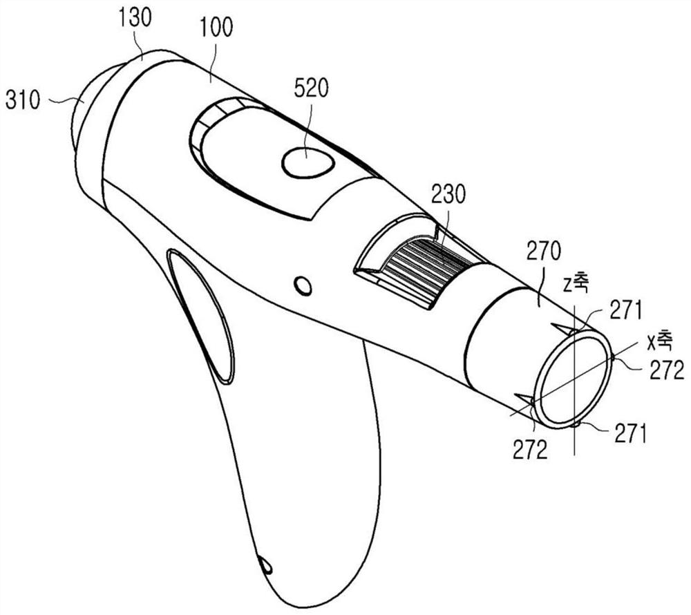
[0042] For convenience, in figure 1 In , the measurement module 200 side is described as the front, and the plasma irradiation module 300 side is described as the rear.

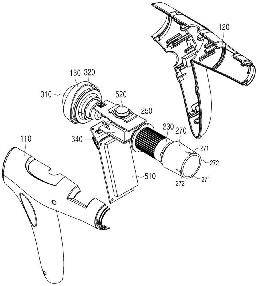
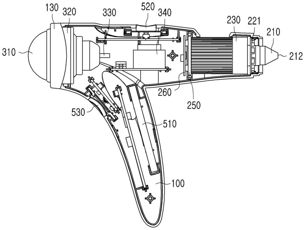
[0043] The plasma device according to the present invention includes a housing 100 , a measurement module 200 , a plasma irradiation module 300 , a photographic activation module 400 and a manipulation module 500 .

[0044] will refer to Figure 1 to Figure 4 Describe the configuration of the plasma device.

[0045] The case 100 covers the internal structure of the plasma apparatus, and includes a first case 110 , a second case 120 and a cover 130 .

[0046] The first case 110 is a case covering one surface of the plasma device, the second case 120 is a case covering the other surface of the plasma device, and the first case 110 and the second case 120 are coupled to each other. .

[00...


PUM


Abstract

The present invention provides a plasma irradiation apparatus, comprising: a housing (100); the measuring module (200) is positioned at one end of the shell (100) and comprises a shooting sensor (261); and a plasma irradiation module (300) located at the other end opposite to the one end of the housing (100), the measurement module (200) comprising: a reflection unit (210) having a lens (211) disposed on the inside thereof and having a reflection hole (212) formed on the surface thereof; a light emitting unit (220) positioned so as to surround the outer periphery of the reflection unit (210); an imaging unit (260) positioned so as to communicate with the inside of the reflecting unit (210) and including an imaging sensor (261); and a lens guide (270) surrounding an outer side of the reflection unit (210) and extending to a position further forward than the reflection unit (210), the lens guide (270) including a plurality of protrusions (271, 272) protruding at intervals in a circumferential direction at the same angle as each other along a leading end of an outer surface of the lens guide (270).

Description

technical field [0001] The invention relates to a device capable of plasma irradiation and skin condition measurement. Background technique [0002] Recently, home care devices that can be easily managed at home without a dermatology department or a separate skin care shop have been developed. The demand for home care equipment is increasing as it is superior in time and cost compared to dermatology and skin care shops. [0003] In addition, there is an increasing demand for measuring devices that can measure skin conditions and skin care devices that can improve skin, in which the measuring devices are in contact with or at a distance from the skin surface to be measured to measure the skin conditions. [0004] At this time, when the user uses the measuring device, the measuring device is kept in a random direction, and the skin is measured in a different direction every time it is used. However, there is a problem that, if the measurement is performed in different direct...

Claims


Application Information

Patent Timeline
IPC IPC(8): A61N1/44A61B5/00
CPCA61N1/44A61B5/441A61B5/0077A61N1/08A61B5/4836
Inventor 李度均
Owner G1合作伙伴有限公司
Learn More