
Energy-saving tail gas desulfurization and dust removal device

A desulfurization and dust removal, energy-saving technology, applied in fixed filter element filters, using liquid separation agents, filtration and separation, etc., can solve the problems of easy clogging of the filter screen, complicated and complicated operation, pollution of the bottom wall, etc., and achieves reasonable and ingenious structural design. Widespread application value and avoid the effect of easy blockage

Inactive Publication Date: 2022-03-01
黄冈融锦化工股份有限公司
View PDF1 Cites 0 Cited by
  • Summary
  • Abstract
  • Description
  • Claims
  • Application Information

AI Technical Summary

Problems solved by technology

[0005] The tail gas enters the interior of the desulfurization tower 1 from the tail gas inlet 102, and the spray system 103 sprays and purifies the tail gas in the tower cavity, and the purified tail gas is discharged from the tail gas discharge port 104. Although this prior art tail gas desulfurization and dust removal device It can treat the tail gas, but there is a serious defect, that is, during the whole purification process, the generated sludge and impurities accumulate on the bottom wall of the tower cavity. If it is not cleaned for a long time, it is easy to cause the bottom wall to be seriously polluted. It cannot be cleaned through the discharge through the sludge outlet or through the discharge outlet. The tower body must be disassembled and the sludge on the bottom wall must be manually scraped off to clean it up. The filter screen is also easy to block, which has great practical application limitations. It is particularly important to develop a device that can scrape away the sludge on the bottom wall of the tower cavity and avoid the blockage of the filter screen at the sewage outlet.

Method used


Image

  • Energy-saving tail gas desulfurization and dust removal device
  • Energy-saving tail gas desulfurization and dust removal device
  • Energy-saving tail gas desulfurization and dust removal device

Examples


Embodiment Construction

[0022] The following will clearly and completely describe the technical solutions in the embodiments of the present invention with reference to the accompanying drawings in the embodiments of the present invention. Obviously, the described embodiments are only some, not all, embodiments of the present invention. Based on the embodiments of the present invention, all other embodiments obtained by persons of ordinary skill in the art without making creative efforts belong to the protection scope of the present invention.

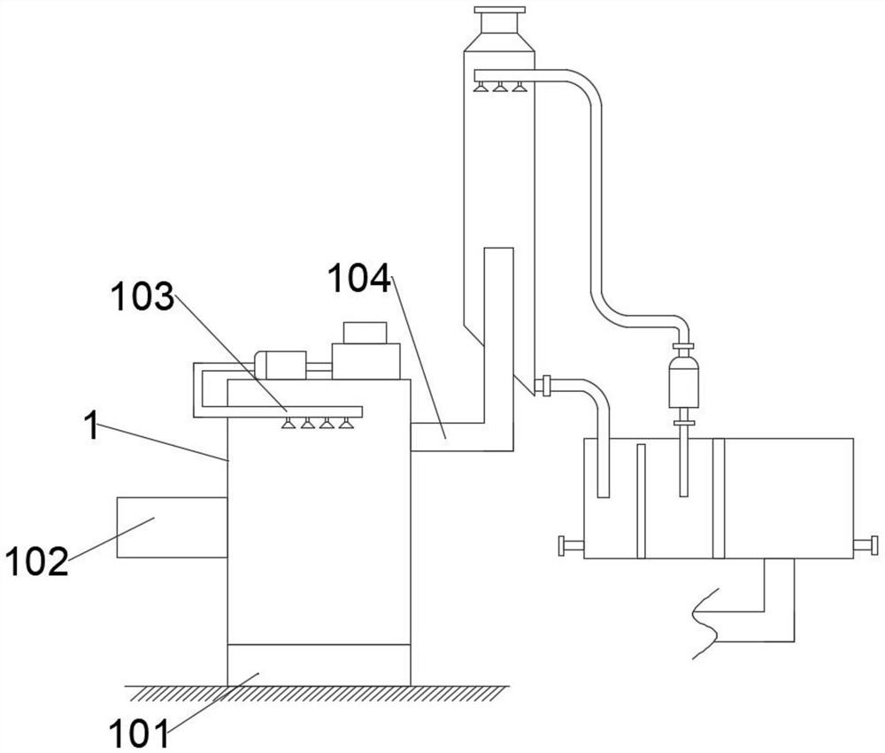
[0023] see figure 1 , figure 1 Indicates a structural schematic diagram of an energy-saving tail gas desulfurization and dust removal device in the prior art. An invention patent with a publication number of CN207153452U and an application number of CN201720984611.3 published on the China Patent Network.

[0024] In this patent, its specific structure includes desulfurization tower 1, tower body base 101, tail gas inlet 102, spray system 103 and tail gas disc...


PUM


Abstract

The invention discloses an energy-saving tail gas desulfurization and dust removal device which comprises a desulfurization tower, a tower body base, a tail gas guide inlet, a spraying system and a tail gas discharge port, a sludge temporary storage tank is formed in a right side base body of the tower body base, a sludge pumping pipeline is horizontally inserted into the sludge temporary storage tank, and a driven bevel gear and a driving bevel gear are in transmission fit together. The driving bevel gear is coaxially and fixedly mounted at the left end of a shaft body of a driving rotating shaft, the driving rotating shaft is driven by a servo motor to operate, a mud scraping blade is correspondingly fixed to the bottom wall face of the synchronous rotating tool apron, and a bristle mounting base is further integrally fixed to a base body on the left side of the upper surface of the synchronous rotating tool apron. Bristles are mounted on the left side wall of the bristle mounting seat and are in contact with the surface of the impurity filter screen. According to the invention, not only can sludge impurities be cleaned, but also the impurity filter screen can be simply brushed.

Description

technical field [0001] The invention relates to the related technical field of tail gas purification equipment, in particular to an energy-saving tail gas desulfurization and dust removal device. Background technique [0002] At present, with the development of social economy and the development of national economy, many development problems are inevitably brought about, such as environmental problems. The deteriorating environment has a serious impact on people's lives, and the country is paying more and more attention to environmental protection Protect. As the main source of environmental pollution, production-oriented enterprises will inevitably produce a large amount of polluting gases due to the requirements of production processes and processes. Such gases often contain acidic sulfuric substances and dust. [0003] see figure 1 , figure 1 Indicates a structural schematic diagram of an energy-saving tail gas desulfurization and dust removal device in the prior art. ...

Claims


Application Information

Patent Timeline
Patent Type & Authority Applications(China)
IPC IPC(8): B01D53/78B01D53/50B01D47/06B01D29/03B01D29/64
CPCB01D53/78B01D53/50B01D47/06B01D29/03B01D29/6415
Inventor 王嫣雨
Owner 黄冈融锦化工股份有限公司
Learn More