Slit coating die head

A technology of slit coating and die head, which is applied to the device and coating of the surface coating liquid, which can solve the problems of holes and uneven thickness of the film, achieve efficient elimination, solve the problem of holes in the film, and improve production efficiency effect

Active Publication Date: 2022-03-01
HUBEI WONDER SOLAR LLC
View PDF14 Cites 0 Cited by
  • Summary
  • Abstract
  • Description
  • Claims
  • Application Information

AI Technical Summary

Problems solved by technology

The slit coating die head of the present invention can efficiently remove the gas inside the die head cavity to solve the problems of holes and uneven thickness of the film caused by air bubbles, thereby improving the accuracy of the coating film

Method used


Image

  • Slit coating die head
  • Slit coating die head
  • Slit coating die head

Examples


Embodiment 1

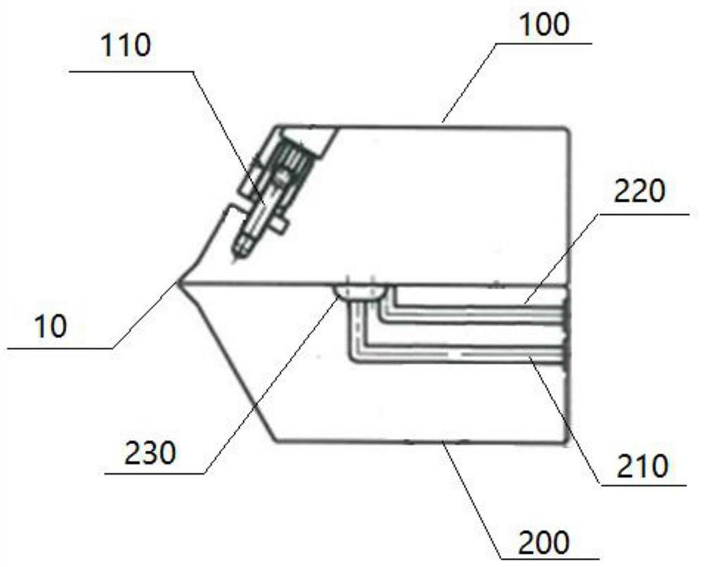
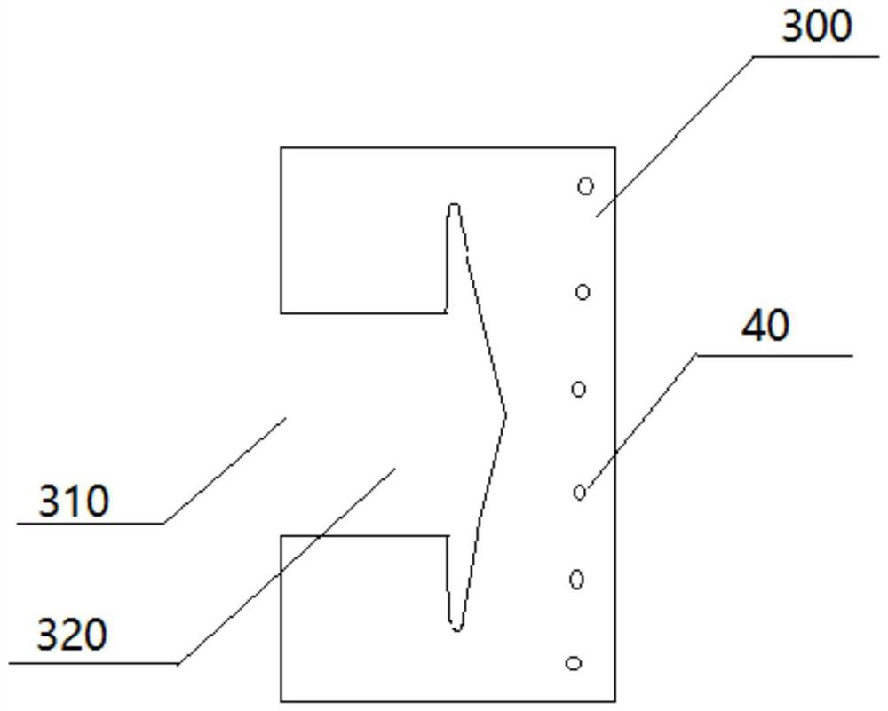
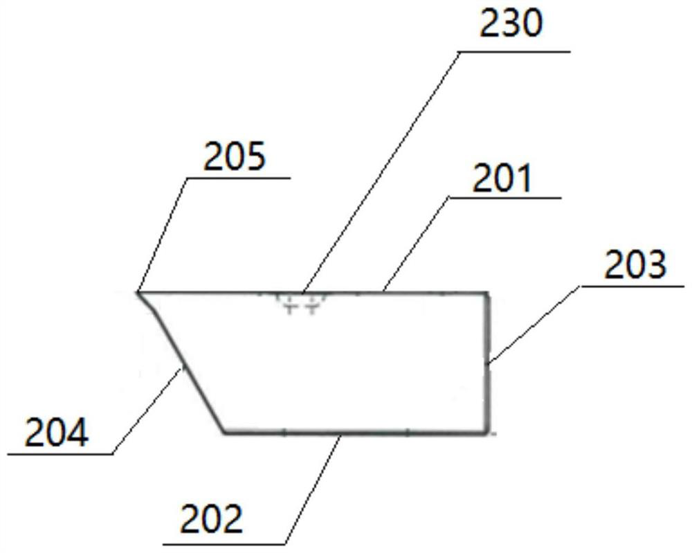
[0067] figure 1 It is a schematic diagram of a section of a slot coating die of the present invention. figure 2 It is a schematic diagram of a gasket of a slot coating die of the present invention. image 3 It is a schematic side view of the lower die of a slit coating die of the present invention. Figure 4 It is a schematic front view of a slit coating die of the present invention.

[0068] Such as Figure 1 ~ Figure 4 As shown, the slot coating die head includes an upper die 100 , a lower die 200 , a gasket 300 between the upper die 100 and the lower die 200 and a two-way switch.

[0069] The lower mold 200 is provided with at least one feed channel 210 , at least one exhaust channel 220 and a material cavity 230 . The exhaust channel 220 is located above the feed channel 210 . The exhaust passage 220 and the feed passage 210 communicate with the material chamber 230 respectively. The feeding channel 210 is used for feeding the coating liquid. The exhaust channel 22...

Embodiment 2

[0080] Except following structure, all the other are identical with embodiment 1:

[0081] Slot dies also include connection blocks and adapters. The connection block is disposed on the positioning and fastening surface 203 , and the connection block is provided with connection holes corresponding to the feed hole 211 and the exhaust hole 221 . The conversion joints are respectively arranged on the connection holes. The two-way switch is connected with the conversion joint corresponding to the exhaust hole, and is used for controlling the opening and closing of the exhaust passage 220 .

Embodiment 3

[0083] Except following structure, all the other are identical with embodiment 2:

[0084] The slit coating die head also includes buckles and beading. Buckles are respectively provided on the first side and the second side of the upper mold 100 and the lower mold 200 . The bead is arranged between the buckle and the first side, and the bead is also arranged between the buckle and the second side, for sealing both sides of the outlet 10 of the slit channel.


PUM

PropertyMeasurementUnit
Thicknessaaaaaaaaaa
Thicknessaaaaaaaaaa

Abstract

The invention discloses a slit coating die head. The slit coating die head comprises an upper die, a lower die and a gasket positioned between the upper die and the lower die, the lower die is provided with at least one feeding channel, at least one exhaust channel and a material cavity, and the exhaust channel is located above the feeding channel; the exhaust channel and the feeding channel are respectively communicated with the material cavity; the feeding channel is used for allowing coating liquid to enter; the exhaust channel is used for exhausting gas in the material cavity; the lower die is further provided with a first protruding part. The upper die is provided with a second protruding part corresponding to the first protruding part; the gasket is provided with an opening and a groove, and the groove is communicated with the opening; a slit channel is formed among the upper die, the groove and the lower die; the material cavity is communicated with the slit channel and is used for circulating coating liquid; a slit channel discharging port is formed among the first protruding part, the opening and the second protruding part and used for allowing coating liquid to flow out for coating. According to the slit coating die head, gas in the die head cavity can be exhausted, and the uniformity of the thickness of an obtained film can be improved.

Description

technical field [0001] The invention relates to a coating die, in particular to a slot coating die head. Background technique [0002] In the research field of printing and coating technology, the mainstream coating technology is mainly spin coating, vacuum evaporation and magnetron sputtering. In the field of commercial mass production, it is mainly based on screen printing, coating, inkjet printing and vacuum evaporation. Slit coating technology is a kind of coating, which can produce high-quality and high-precision films in a non-contact coating method, which is of great significance in the field of precision functional film production. [0003] The film quality of the traditional slit coating technology cannot meet the high precision requirements. Especially in the slit coating process, there is usually a situation where the fluid is easily mixed with air bubbles inside the die cavity, which will cause holes in the coating film and uneven thickness, which will affect t...

Claims


Application Information

Patent Timeline
IPC IPC(8): B05C5/00
CPCB05C5/005
Inventor 韩宏伟盛余松程浩
Owner HUBEI WONDER SOLAR LLC
Why Eureka
Try Eureka