Tire lining layer manufacturing method

A manufacturing method and a technology for an inner liner, which are applied in the field of tire manufacturing, can solve the problems of unstable processing dimensions, frequent replacement of tooling, difficult production processes, etc., so as to improve the calendering production accuracy, reduce the maximum calendering width, and improve the quality of tire finished products. Effect

Pending Publication Date: 2022-03-01
SAILUN GRP CO LTD
View PDF0 Cites 0 Cited by
  • Summary
  • Abstract
  • Description
  • Claims
  • Application Information

AI Technical Summary

Problems solved by technology

[0004] The purpose of the present invention is to solve the above-mentioned problems existing in the prior art, and propose a tire inner liner manufacturing method suitable for all steel radial engineering tires, by changing the inner liner application process, to solve the problem of the current inner liner production Encountered difficult problems such as unstable processing dimensions, frequent tooling replacement and low efficiency; the new lining layer application method provided by the present invention can reduce the calendered size of the airtight layer and transition layer, and improve production efficiency ;It can reduce the maximum width of calendering, which is beneficial to control the thickness of the airtight layer or transition layer film at the same time; because the maximum width of calendering is reduced, the corresponding equipment size requirements are reduced, thereby greatly reducing equipment costs

Method used


Image

  • Tire lining layer manufacturing method
  • Tire lining layer manufacturing method
  • Tire lining layer manufacturing method

Examples


Embodiment 1

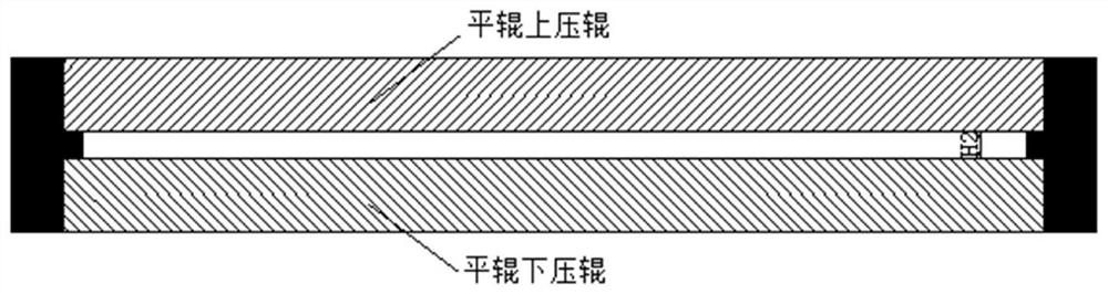
[0039] like Figure 5 As shown, for products whose total width of the inner liner is less than 1000mm, the airtight layer and the transition layer are calendered with rolls, directly calendered and extruded, and then applied together.

Embodiment 2

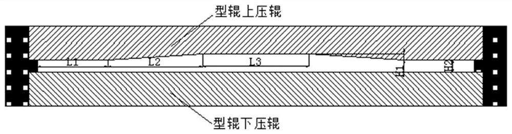
[0041] like Figure 6 As shown, for products with a total width of the inner lining layer of more than 1000mm, the product size is less than 23.5R25, and the calender cannot calender the inner liner and transition layer at one time, the following operations should be performed:

[0042] 1) Roll out inner liner 1, transition layer 1, inner liner 2, and transition layer 2 with flat rollers respectively (the width of inner liner 1 is smaller than that of inner liner 2, and the width of transition layer 1 is greater than transition layer 2), and calendered with molded rolls Exit airtight layer 3, transition layer 3;

[0043] 2) The first layer is formed by splicing airtight layers 1 and 2, and the overlapping width in the middle is 10-20mm;

[0044] 3) Arrange in the second layer with airtight layer 3;

[0045] 4) Row the third layer with transition layer 3;

[0046] 5) The transition layer 1 and 2 are spliced ​​to form the fourth layer, and the width of the middle lap is 10-20mm...

Embodiment 3

[0049] like Figure 7 As shown, for products with a total inner liner width of more than 1000mm, the size of the product is between 23.5R25 and 29.5R25, the calender cannot roll out the inner liner and transition layer at one time, and only two layers of the inner liner cannot meet its thickness. (When the edge thickness of the airtight layer is greater than 4.0mm, it will cause edge delamination), you need to add a layer of airtight layer, as follows:

[0050] 1) Roll out the inner liner 1, the transition layer 1, the inner liner 2, and the transition layer 2 with flat rollers respectively (the width of the inner liner 1 is greater than that of the inner liner 2, and the width of the transition layer 1 is greater than that of the transition layer 2). Roll out inner liner 4, inner liner 5 (the width of inner liner 4 is less than inner liner 5), roll out inner liner 3, transition layer 3 with molded roller calendering;

[0051] 2) Use airtight layers 1 and 2 to form the first ...


PUM


Abstract

The invention belongs to the technical field of tire manufacturing, and particularly relates to a tire lining layer manufacturing method which comprises the following two modes: mode 1, when the total width of a lining layer is smaller than 1000mm, the lining layer is directly pressed and applied together by adopting a calendaring method; in the second mode, when the total width of the lining layer is larger than or equal to 1000 mm, the lining layer is pasted with a needed rubber sheet in advance for calendaring, a forming roller calendaring rubber sheet and a flat roller calendaring rubber sheet are obtained, then at least one layer of forming roller calendaring rubber sheet and at least one layer of flat roller calendaring rubber sheet are selected according to the thickness requirement of the tire, and the lining layer is pasted into a corresponding shape; and the lining layer composite part is obtained. According to the lining layer application mode provided by the invention, the calendering sizes of the airtight layer and the transition layer can be reduced, and the production efficiency is improved; the maximum calendering width can be reduced, and the thickness of an airtight layer or a transition layer film can be controlled at the same time; and meanwhile, the maximum calendering width is reduced, so that the equipment size requirement is reduced, and the equipment cost is greatly reduced.

Description

technical field [0001] The invention belongs to the technical field of tire manufacturing, and in particular relates to a tire inner liner manufacturing method, which is applicable to all all-steel radial engineering tire products. Background technique [0002] In all-steel radial OTR tires, the inner liner is usually composed of an inner liner and a transition layer. The inner liner can prevent moisture and gas from permeating, thereby achieving the effect of maintaining pressure. The transition layer is used to strengthen the inner liner and transition layer. Adhesion between other components, preventing delamination of components. In the prior art, a calender is used to extrude the airtight layer and the transition layer and then bond them together to form the inner liner composite. The extrusion width of the general inner lining calender is less than 1000mm. Once it exceeds 1000mm, the calendering will be very difficult; when controlling the thickness of the edge, it is...

Claims


Application Information

Patent Timeline
Patent Type & Authority Applications(China)
IPC IPC(8): B29D30/08
CPCB29D30/08
Inventor 张红斌田建成仝传贤
Owner SAILUN GRP CO LTD
Why Eureka
Try Eureka