
Coal-to-liquid tail oil treatment equipment and method

A treatment equipment and coal-to-oil technology, which is applied in the treatment of hydrocarbon oil, wax physical treatment, petroleum industry, etc., can solve problems such as complicated procedures and operations, difficulty in guaranteeing the quality of wax oil, and inability to extract oil, so as to achieve stable quality, Simple operation, easy to adjust and control the effect

Pending Publication Date: 2022-03-01
SHANXI LUAN COAL BASED CLEAN ENERGY
View PDF0 Cites 0 Cited by
  • Summary
  • Abstract
  • Description
  • Claims
  • Application Information

AI Technical Summary

Problems solved by technology

Now to change the freezing point of the wax oil extracted from the bottom of the vacuum tower, adjust the temperature in the atmospheric fractionation tower and the vacuum tower to change the final boiling point of the oil entering the vacuum tower, and change the temperature of the atmospheric fractionation tower. Line, diesel oil extraction pipeline of vacuum tower and heavy firewood extraction pipeline to adjust the freezing point of the wax oil finally extracted from the bottom of vacuum tower. The existing method has complicated procedures and operations, and frequent operations will increase production. Safety risk; and the oil pumped out by each line is mostly stored in the storage tank. Due to the impact of the storage capacity of the storage tank, it may happen that the line needs to suspend oil pumping or cannot pump out oil after a certain storage tank is full. The extraction volume is difficult to control stably, because the extraction volume of each line affects the quality of the wax oil. In the prior art, the quality of the wax oil extracted from the bottom oil pipeline of the vacuum tower is difficult to guarantee

Method used


Image

  • Coal-to-liquid tail oil treatment equipment and method

Examples


Embodiment Construction

[0037] In order to make the object, technical solution and advantages of the present invention clearer, the present invention will be further described in detail below in conjunction with the accompanying drawings.

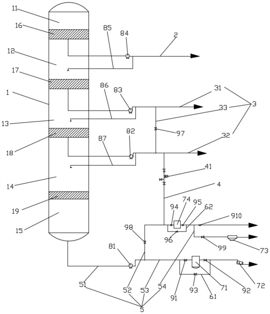
[0038] Such as figure 1 As shown, the embodiment of the coal-to-oil tail oil treatment equipment disclosed in the present invention includes a vacuum tower 1 and a regulating pipe 4, and the vacuum tower 1 has an input port, a diesel extraction pipeline 2, a heavy diesel extraction pipeline 3 and a bottom oil pipeline 5. The decompression tower 1 communicates with the front-end equipment through the input port. The front-end equipment transports the oil to the decompression tower 1 through the input port. The input end of the diesel extraction pipeline 2 communicates with the upper part of the decompression tower 1. The input end of 3 communicates with the middle part of the decompression tower 1, the input end of the bottom oil pipeline 5 communicates with the bo...


PUM


Abstract

The invention discloses coal-to-oil tail oil treatment equipment which comprises a vacuum tower and an adjusting pipe, the vacuum tower is provided with an input port, a diesel oil extraction pipeline, a heavy diesel oil extraction pipeline and a bottom oil pipeline, the vacuum tower is communicated with front-end equipment through the input port, and the front-end equipment conveys an oil product into the vacuum tower through the input port; the input end of the diesel oil extraction pipeline is communicated with the upper portion of the vacuum tower, the input end of the heavy diesel oil extraction pipeline is communicated with the middle of the vacuum tower, the input end of the bottom oil pipeline is communicated with the bottom of the vacuum tower, the heavy diesel oil extraction pipeline is communicated with the bottom oil pipeline through the adjusting pipe, and the adjusting pipe is provided with an adjusting valve set. The invention further discloses a coal-to-liquid tail oil treatment method. According to the coal-to-liquid tail oil treatment equipment and method provided by the invention, the condensation point of the extracted wax oil can be quickly adjusted, the adjustment and control are convenient, the safety is higher, and the stability of the quality of the wax oil extracted from the bottom of the vacuum tower can be ensured.

Description

technical field [0001] The invention relates to the field of coal-to-oil production, in particular to equipment and methods for treating tail oil from coal-to-oil. Background technique [0002] Coal-to-liquids is a technology that uses coal as raw material to produce oil products and petrochemical products through chemical processing. Under the working conditions of hydrofining, the produced oil passes through the atmospheric fractionation tower to separate the light oil and gas, and the remaining oil enters the vacuum tower, where the remaining oil is further processed. The upper and middle parts of the vacuum tower The diesel oil extraction pipeline, the heavy firewood extraction pipeline and the bottom oil pipeline are respectively connected to the bottom of the decompression tower. The wax oil at the bottom of the tower is pumped out through the bottom oil pipeline. Due to the different requirements for the freezing point of the wax oil extracted from the bottom oil pi...

Claims


Application Information

Patent Timeline
IPC IPC(8): C10G73/40C10G7/12C10G7/06
CPCC10G73/40C10G7/12C10G7/06C10G2300/304
Inventor 蔡俊艳王智屈飞于少华聂鹏扬赵旭耀裴宏宇张文奎
Owner SHANXI LUAN COAL BASED CLEAN ENERGY
Learn More