Monitoring device with smoke exhaust function for building automation

A technology for building automation and monitoring devices, which is applied in the direction of exhaust gas exhaust devices, valve operation/release devices, valve devices, etc. It can solve the problems of no smoke exhaust components, low smoke exhaust efficiency, and small smoke absorption area. Achieve good protection, improve efficiency, and prevent damage to life

Pending Publication Date: 2022-03-01
NANJING VOCATIONAL UNIV OF IND TECH
View PDF0 Cites 0 Cited by
  • Summary
  • Abstract
  • Description
  • Claims
  • Application Information

AI Technical Summary

Problems solved by technology

[0004] The purpose of the present invention is to provide a monitoring device with a smoke exhaust function for building automation, to solve the problem in the above-mentioned background technology that most of the existing smoke monitoring devices do not have a smoke exhaust component, and only produce smoke to the smoke. At the same time, in the existing smoke exhaust structure, most of them are fixedly installed on the ceiling, and the smoke absorption area is small, which makes the smoke exhaust efficiency low.

Method used


Image

  • Monitoring device with smoke exhaust function for building automation
  • Monitoring device with smoke exhaust function for building automation
  • Monitoring device with smoke exhaust function for building automation

Examples


Embodiment Construction

[0037] The following will clearly and completely describe the technical solutions in the embodiments of the present invention with reference to the accompanying drawings in the embodiments of the present invention. Obviously, the described embodiments are only some, not all, embodiments of the present invention. Based on the embodiments of the present invention, all other embodiments obtained by persons of ordinary skill in the art without making creative efforts belong to the protection scope of the present invention.

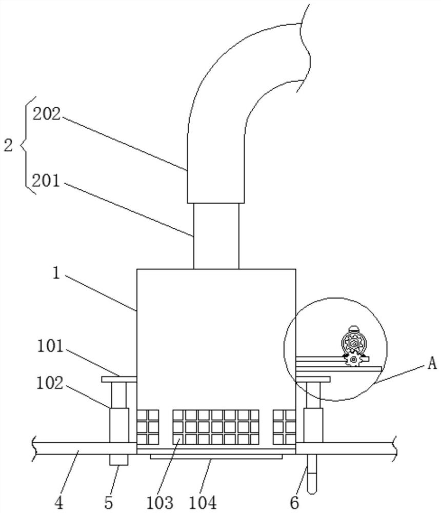
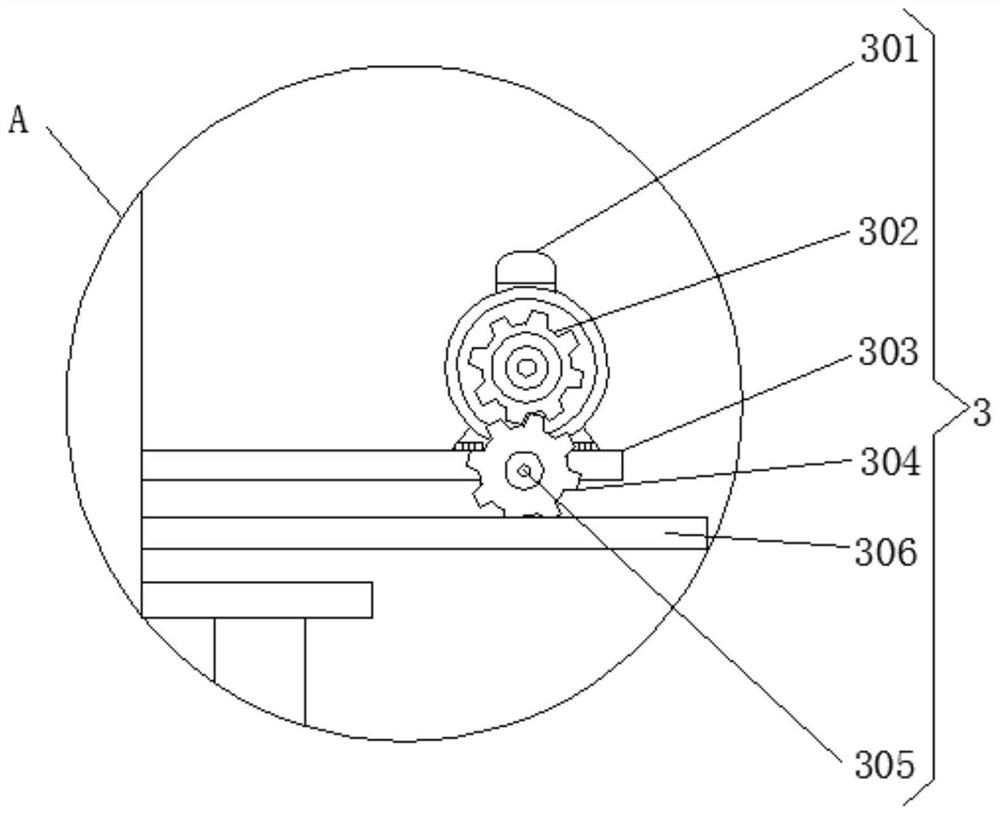
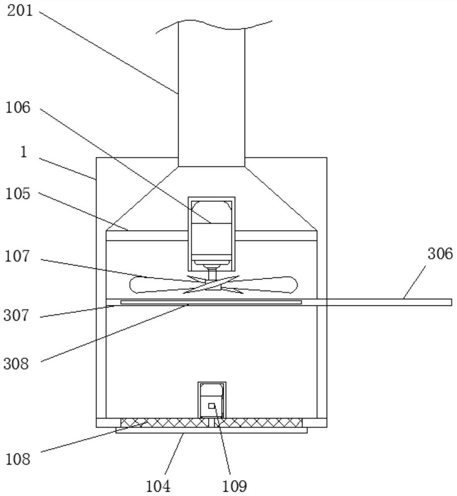
[0038] see Figure 1-6 , the present invention provides a technical solution: a monitoring device with smoke exhaust function for building automation, according to figure 1 , image 3 and Figure 4As shown, the smoke exhaust box 1 includes an outer connecting plate 101, an electric telescopic rod 102, a side screen 103, a scraper 104, a mounting frame 105, a first drive motor 106, a smoke exhaust fan 107, a bottom screen 108 and a second Drive motor 109, ex...


PUM


Abstract

The invention discloses a building automation monitoring device with a smoke discharge function, which comprises a smoke discharge box body, an air guide pipe and a baffle plate structure, outer connecting plates are mounted on two sides of the outside of the smoke discharge box body, electric telescopic rods are arranged at the bottoms of the outer connecting plates, the bottoms of the electric telescopic rods are fixed at the top of a ceiling, and the air guide pipe is arranged on the top of the smoke discharge box body. A smoke exhaust fan is installed on an output shaft of the first driving motor, a bottom net plate is arranged at the bottom of the smoke exhaust box body, the air guide pipe is arranged at the top of the smoke exhaust box body, and the baffle structure is arranged on the side face of the smoke exhaust box body. The monitoring device with the smoke exhaust function for building automation is provided with an outer connecting plate, an electric telescopic rod and a side net plate, the electric telescopic rod drives the smoke exhaust box body to ascend and descend through the outer connecting plate, and then when a smoke sensor detects a smoke signal, the electric telescopic rod shrinks, so that the smoke exhaust box body descends, and the side net plate on the side face of the smoke exhaust box body is exposed; therefore, the smoke suction area is increased, and the smoke exhaust efficiency is improved.

Description

technical field [0001] The invention relates to the technical field of building automation, in particular to a monitoring device with smoke exhaust function for building automation. Background technique [0002] In modern construction projects, fire alarm systems are generally installed, but when a fire really comes, the pervasive smoke is the chief culprit of death. Among the people who died in the fire, the people who died of smoke accounted for The ratio is as high as 80%, so in the early stage of the fire, that is, when the firefighters arrive in the future, an effective smoke exhaust system will greatly increase the survival probability of the victims, so it is necessary to design smoke monitoring and smoke exhaust devices. [0003] However, in the existing smoke monitoring devices, most of them do not have a smoke exhaust component, and only generate an alarm for the smoke. Small, so that the smoke exhaust efficiency is low, so the existing structure needs to be impro...

Claims


Application Information

Patent Timeline
IPC IPC(8): F23J11/12F23J15/02B01D46/681F16K3/02F16K31/04F16K31/54
CPCF23J11/12F23J15/025F16K3/02F16K31/04F16K31/54F23J2217/10
Inventor 何松原高武铉
Owner NANJING VOCATIONAL UNIV OF IND TECH
Why Eureka
Try Eureka