Method for arranging microwave emitters on outer peripheral surface of rotary kiln body

A microwave transmitter and microwave generator technology, which is applied in the direction of rotary drum furnace, lighting and heating equipment, electric furnace heating, etc., can solve the problem of low thermal efficiency utilization rate of microwave generator, unsuccinct thermal efficiency, unreasonable position setting and line direction and other problems, to achieve the effect of simple and orderly layout, improve thermal efficiency utilization, and avoid injury accidents

Pending Publication Date: 2022-03-01
株洲聚润合微波工业炉有限公司
View PDF8 Cites 0 Cited by
  • Summary
  • Abstract
  • Description
  • Claims
  • Application Information

AI Technical Summary

Problems solved by technology

[0008] The technical problem to be solved by the present invention is mainly: how to solve the problems of unreasonable, unsuccinct and low thermal efficiency of the microwave generator outside the microwave rotary kiln, its power line, and the position setting of the power receiving device and the direction of the line
[0009] In view of the above problems, the technical solution proposed by the present invention is: how to solve the problem of low thermal efficiency utilization rate of the microwave generator outside the microwave rotary kiln kiln

Method used


Image

  • Method for arranging microwave emitters on outer peripheral surface of rotary kiln body
  • Method for arranging microwave emitters on outer peripheral surface of rotary kiln body
  • Method for arranging microwave emitters on outer peripheral surface of rotary kiln body

Examples


Embodiment Construction

[0029] Below in conjunction with embodiment and accompanying drawing, the present invention will be further described:

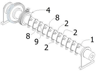
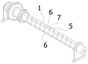
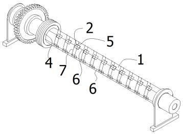
[0030] Such as figure 1 , 3 As shown, a method of arranging a microwave transmitter on the peripheral surface of a rotary kiln body is to arrange a plurality of wave feed ports 2 on the outer peripheral surface of a cylindrical kiln body 1, and to install wave feed ports 2 on each wave feed port 2 that can follow the kiln The microwave generator 3 that the body 1 rotates is set on the kiln body 1 at the same time, the power receiving device 4 that can accept the external power supply under the working condition of the kiln body rotating, and the power line connecting the power receiving device 4 and the microwave generator. The power line is a general term for one neutral line and one to three live lines. In this case, the power cord includes a neutral wire and three live wires. In this way, by installing the microwave generator 3 directly on the wave fee...


PUM


Abstract

The invention discloses a method for arranging microwave emitters on the outer peripheral surface of a rotary kiln body, which comprises the following steps of: arranging a plurality of wave feed ports on the outer peripheral surface of a cylindrical kiln body, mounting microwave generators capable of rotating along with the kiln body on the wave feed ports, and arranging a power receiving device capable of receiving an external power supply on the kiln body under the working condition that the kiln body rotates, and the power line is communicated with the power receiving device and the microwave generator. A plurality of wave feeding openings are formed in the peripheral face of the kiln body, and each wave feeding opening independently occupies one section of the kiln body on the periphery of the cylindrical kiln body. The microwave generator has the advantages that compared with a traditional wave feeding mode, complete sealing of the microwave generator and the wave feeding opening is achieved, the heat efficiency utilization rate of the microwave generator is remarkably improved, and meanwhile injury accidents caused by microwave leakage can be completely avoided; the directions of microwaves emitted by the microwave generators are not aligned and not intersected, microwave interference offset and ignition are avoided, and the microwave heat efficiency utilization rate can be further improved.

Description

technical field [0001] The invention relates to a method for arranging microwave emitters on the peripheral surface of a rotary kiln body, and belongs to the technical field of rotary kiln electric heating. Background technique [0002] With the development of microwave technology, its application has begun to expand to the field of rotary kiln heating to replace coal and other fuels for heat generation. However, due to the short application time of microwave in the field of rotary kiln, the microwave rotary kiln that has been developed and formed has unreasonable position setting, power connection mode and line direction of the microwave generator and its power line, power receiving device involved in the kiln body , Unreliable, and not simple, resulting in low thermal efficiency utilization of microwave rotary kiln, unsafe electricity consumption, and high processing and maintenance costs. [0003] By searching, obtain the following patent documents closest to the present...

Claims


Application Information

Patent Timeline
Patent Type & Authority Applications(China)
IPC IPC(8): F27B7/08F27B7/34F27D11/06
CPCF27B7/08F27B7/34F27D11/06
Inventor 胡俊旭何秋刘辉汉
Owner 株洲聚润合微波工业炉有限公司
Why Eureka
Try Eureka