
Three-dimensional negative stiffness elastic frame

An elastic frame and negative stiffness technology, applied in the field of aircraft deformation, can solve the problems of large driving force and high energy consumption, and achieve the effect of small driving force demand, low energy consumption, and flexible and diverse applications

Pending Publication Date: 2022-03-01
HARBIN INST OF TECH
View PDF9 Cites 0 Cited by
  • Summary
  • Abstract
  • Description
  • Claims
  • Application Information

AI Technical Summary

Problems solved by technology

[0005] The purpose of the present invention is to solve the problem that the greater the deflection angle of the missiles controlled by the deflection head, the greater the required driving force and the greater the energy consumption, a three-dimensional negative stiffness elastic frame is provided, and its technical solution is as follows:

Method used


Image

  • Three-dimensional negative stiffness elastic frame
  • Three-dimensional negative stiffness elastic frame
  • Three-dimensional negative stiffness elastic frame

Examples


Embodiment 1

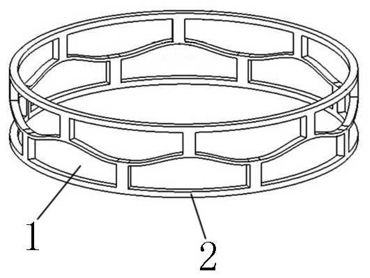
[0018] Embodiment 1, the top beam 2-1 and / or the bottom beam 2-2 remaining around each hollow 1 arranged in the shape of a square on the cylinder wall 2 is an outwardly convex curved beam. When the warhead needs to deflect upward, the upper side It only needs to shrink the deflection drive mechanism 3 to compress the upper side of the cylinder wall 2 .

Embodiment 2

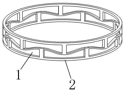
[0019] Embodiment 2, the top beam 2-1 and / or the bottom beam 2-2 remaining around each hollow 1 arranged in the character shape of the cylinder wall 2 is a concave curved beam, and when the warhead needs to deflect upward, the bottom beam 2-1 located on the lower side The extension of the deflection drive mechanism 3 only needs to extend the lower side of the cylinder wall 2 .

Embodiment 3

[0020] In the third embodiment, the cylinder wall 2 includes both a convex curved beam hollow section and a concave curved beam hollow section, so that the deflection drive control is more flexible. The convex curved beam hollow section 1 and the concave curved beam hollow section 1 can be flexibly matched according to needs. Set the convex curved beam hollow section 1 as A, and the concave curved beam hollow section 1 as B. ABAB, ABBA, BAAB and other methods can be matched freely.

[0021] Preferably, the continuous curved beam is a cosine waveform, and the deformation and recovery are relatively smooth.

[0022] The material of the cylinder wall 2 can be metal, such as aluminum alloy, steel, etc., or fiber, such as carbon fiber, graphene fiber, carbon nanotube fiber and other reinforced composite materials.


PUM


Abstract

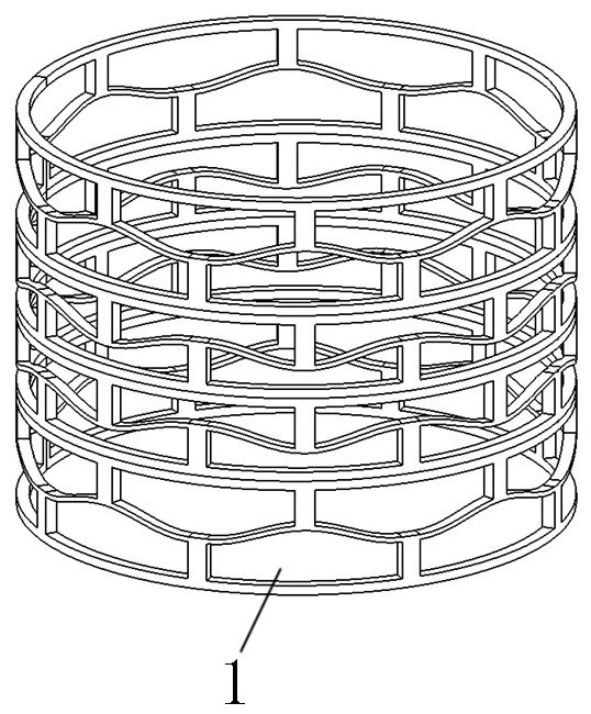
A three-dimensional negative-stiffness elastic frame belongs to the technical field of aircraft deformation, solves the problem of high energy consumption of an existing bullet controlled by a deflection head, and comprises a cylinder wall provided with a plurality of hollowed-out parts, the hollowed-out parts are arranged in a delta shape, and the left-right direction of the delta shape is arranged in the circumferential direction of the cylinder wall; the cylinder can be a cylinder, an elliptical cylinder, a square cylinder, a polygonal cylinder and the like, or a straight cylinder, a bent cylinder, a reducing cylinder and the like in any shape, and can be arranged according to the requirements of the head of the aircraft; due to the fact that the hollowed-out parts arranged in the shape like the Chinese character'pin 'are formed in the cylinder wall and are arranged in the circumferential direction of the cylinder wall, the cylinder wall can have the axial elastic deformation function like a spring, and overall deflection can be achieved. The above technology is the prior art. The cylinder wall reserved around each hollowed-out part arranged in the shape like the Chinese character'pin 'comprises a top beam, a bottom beam and vertical beams on the two sides; the top beam and / or the bottom beam reserved around each hollowed-out part arranged in the shape like the Chinese character'pin' are outwards convex or inwards concave curved beams; the method is used for aircraft deformation.

Description

technical field [0001] The invention belongs to the technical field of aircraft deformation, and in particular relates to a three-dimensional negative stiffness elastic frame. Background technique [0002] The flight control of aircraft such as ordinary bullets and arrows is mainly realized through the tail and canard. The canard located at the arrowhead can change the aerodynamic force to control the flight attitude through the rotation of the rudder blade, but the canard is easily affected by the shock wave at the arrowhead. Thereby reducing the control efficiency, and the existence of the canard will increase the resistance of the projectile body and interfere with the empennage, thereby adversely affecting its flight control. [0003] The deflection head control method is a unique missile control method. By changing the angle between the head and the axis of the missile body, the control torque can be generated through the pressure difference between the windward side an...

Claims


Application Information

Patent Timeline
IPC IPC(8): F42B10/00F42B10/60
CPCF42B10/00F42B10/60
Inventor 李鹏尹维龙王进李建军李宜彬
Owner HARBIN INST OF TECH
Learn More