
Method and system for generating tool path with normal machining allowance

A technology of machining allowance and normal vector, applied in general control system, control/adjustment system, comprehensive factory control, etc., can solve the problems of low efficiency and accuracy of manual calculation, simplify the steps of manual calculation of allowance and improve accuracy degree, the effect of improving efficiency

Active Publication Date: 2022-03-01
ZWCAD SOFTWARE CO LTD
View PDF10 Cites 0 Cited by
  • Summary
  • Abstract
  • Description
  • Claims
  • Application Information

AI Technical Summary

Problems solved by technology

However, the selection of existing machining allowances is generally obtained by manual calculation. The calculated machining allowances are then entered into the control system to allow the machine to process parts according to the preset allowances. However, the efficiency and accuracy of manual calculations are low. relatively low

Method used


Image

  • Method and system for generating tool path with normal machining allowance
  • Method and system for generating tool path with normal machining allowance
  • Method and system for generating tool path with normal machining allowance

Examples


Embodiment 1

[0054] This embodiment provides a tool path generation method with normal machining allowance, which can offset the STL model outward along the surface normal direction to generate a model with allowance, which can be directly used with normal machining allowance The tool path is generated to improve the machining efficiency of parts.

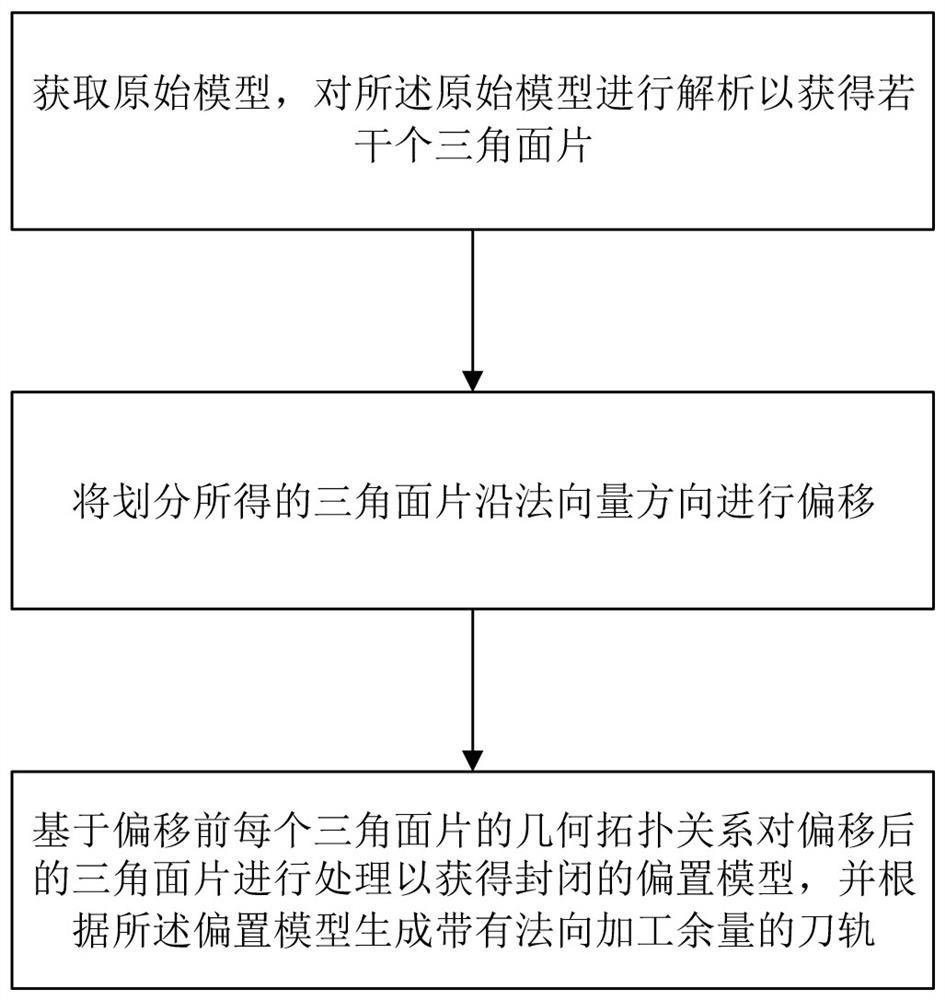
[0055] like figure 1 As shown, the tool path generation method with normal machining allowance in this embodiment specifically includes:

[0056] Step S1: Obtain the original model, and analyze the original model to obtain several triangle faces;

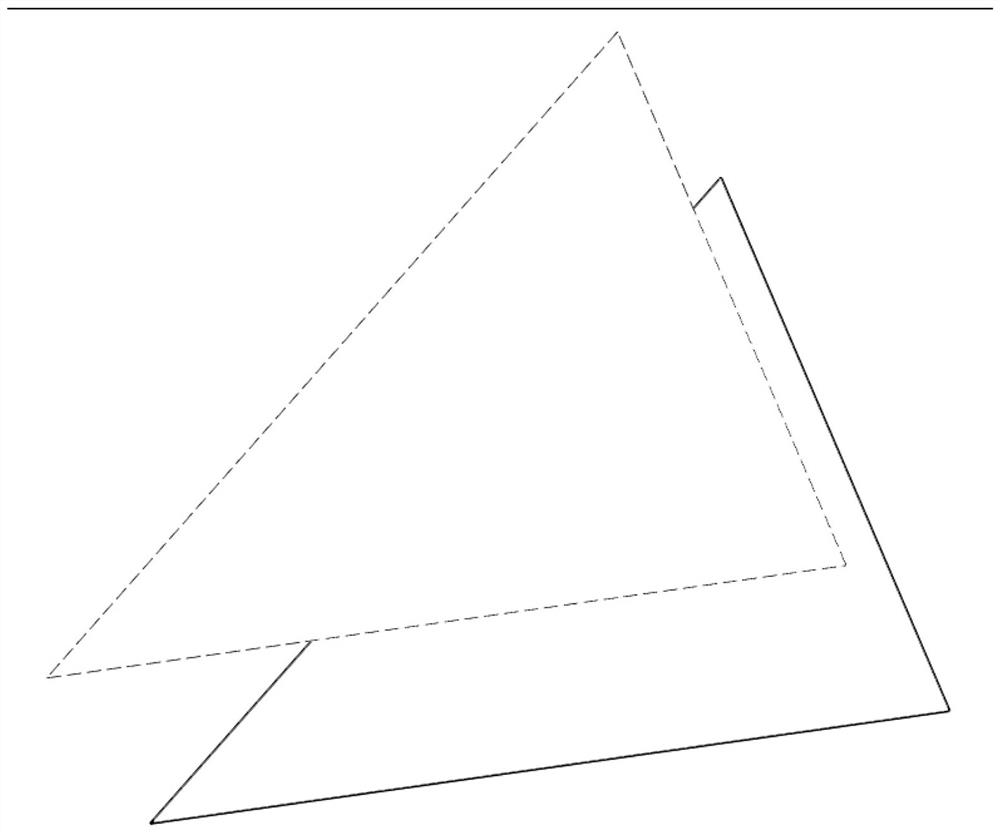
[0057] Step S2: Offset the divided triangular patch along the direction of the normal vector;

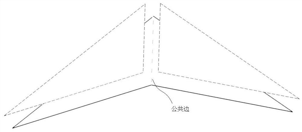
[0058] Step S3: Based on the geometric topological relationship of each triangular patch before migration, process the triangular patch after migration to obtain a closed normal offset model, and generate a Toolpath for machining allowance.

[0059] The original model input in this embodiment is a clos...

Embodiment 2

[0080] This embodiment provides a tool path generation system with normal machining allowance, which implements the tool path generation method with normal machining allowance as described in Embodiment 1, including:

[0081] A model parsing module, configured to obtain an original model, and analyze the original model to obtain several triangular faces;

[0082] The patch offset module is used to offset the divided triangle patch along the normal vector direction;

[0083] The model generation module is used for filling the gaps and clipping overlapping parts of the triangular patches after migration based on the geometric topological relationship of each triangular patch before the migration to obtain a closed normal bias model;

[0084] The tool path generation module is used to generate a tool path with a normal machining allowance according to the normal offset model.

[0085] This embodiment also provides an electronic device, which includes a processor, a memory, and a...


PUM


Abstract

The invention discloses a method and system for generating a tool path with normal machining allowance, and the process for generating the tool path with the normal machining allowance comprises the steps: obtaining an original model, and analyzing the original model to obtain a plurality of triangular patches; the triangular patches obtained through division are shifted in the normal vector direction; and the offset triangular patches are processed based on the geometric topological relation of the triangular patches before offset so as to obtain a closed normal offset model, and a corresponding tool path with normal machining allowance is generated according to the normal offset model. According to the method, the original model is automatically biased in the normal direction of the surface of the model, then the tool path with the normal machining allowance is directly generated according to the normal biased model, the step of manually calculating the allowance is simplified, the precision degree of part machining can be improved, and the part machining efficiency is improved.

Description

technical field [0001] The invention relates to the technical field of numerical control machining, in particular to a method, system, device and storage medium for generating a tool path with a normal machining allowance. Background technique [0002] In the field of NC machining, the user needs to input the part model, generate all the cutter location surfaces (Cutter Location, hereinafter referred to as CL surface) according to the part model, and then use the points on the cutter location surface according to the parallel tool path, offset tool path, etc. Style connections form tool paths; the basic idea of ​​generating CL surfaces is to drop the tool along the tool axis until it touches the model. [0003] In the actual processing scene, the processing of parts basically needs to be performed in the order of rough machining, second roughing, semi-finishing, and finishing. Except for the machining allowance of the last step of finishing, which is 0 to ensure that it is c...

Claims


Application Information

Patent Timeline
IPC IPC(8): G05B19/19G06F30/23G06F30/17
CPCG05B19/19G06F30/23G06F30/17G05B2219/34202Y02P90/02
Inventor 黄亮陈绍磊陈锦斌何寒冰甘文峰冯征文
Owner ZWCAD SOFTWARE CO LTD
Learn More