Eureka AIR delivers breakthrough ideas for toughest innovation challenges, trusted by R&D personnel around the world.

Bumper for vehicle

A bumper and vehicle technology, applied in the field of bumpers and vehicle bumpers, can solve the problems of high cost of manufacturing solutions, and achieve the effect of simple cost, low manufacturing method, stable and reliable manufacturing

Pending Publication Date: 2022-03-01
BAYERISCHE MOTOREN WERKE AG
View PDF8 Cites 0 Cited by
  • Summary
  • Abstract
  • Description
  • Claims
  • Application Information

AI Technical Summary

Problems solved by technology

However, the cost of manufacturing solutions using deep-drawing tools is very high
Furthermore, the transformation of the geometry is only possible to a limited extent, since a profile bevel is always provided

Method used


Image

  • Bumper for vehicle
  • Bumper for vehicle

Examples


Embodiment Construction

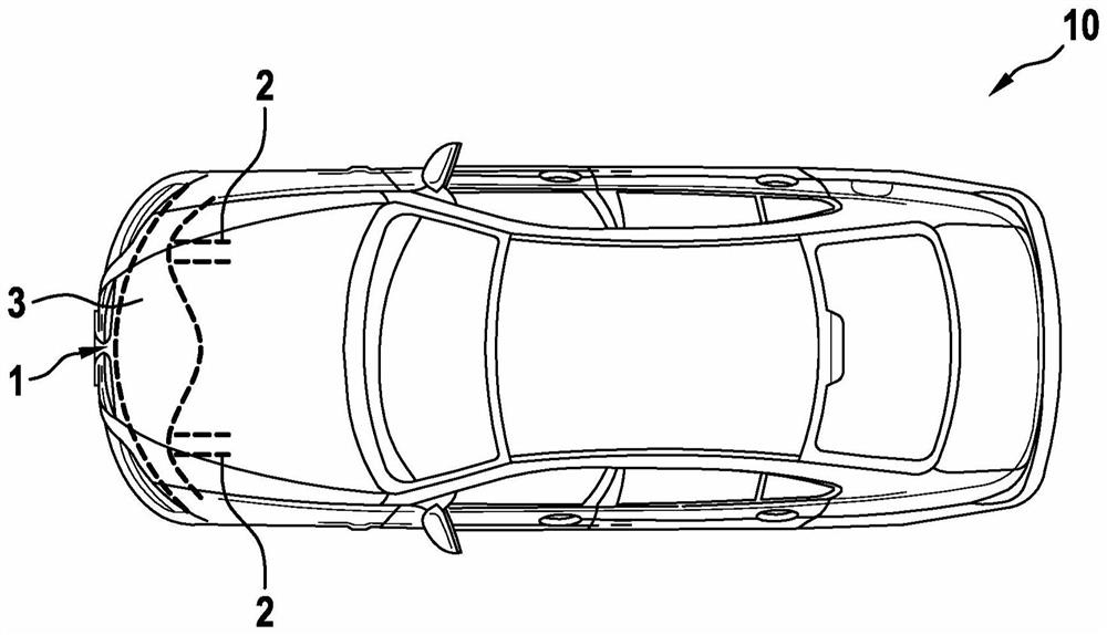
[0018] figure 1 A vehicle 10 according to one embodiment of the invention is schematically shown. At the front of the vehicle, the vehicle 10 has a bumper 1 which in turn includes two side members 2 and a cross member 3 . The bumper 1 is in particular configured symmetrically with respect to the longitudinal axis of the vehicle.

[0019] If the front of the vehicle hits an obstacle, forces can be introduced from the cross member 3 into the side member 2 . The side members 2 are preferably designed as crash boxes for absorbing crash energy.

[0020] Likewise, as at the front of the vehicle, the bumper 1 can also be installed at the rear of the vehicle in order to also absorb crash energy there.

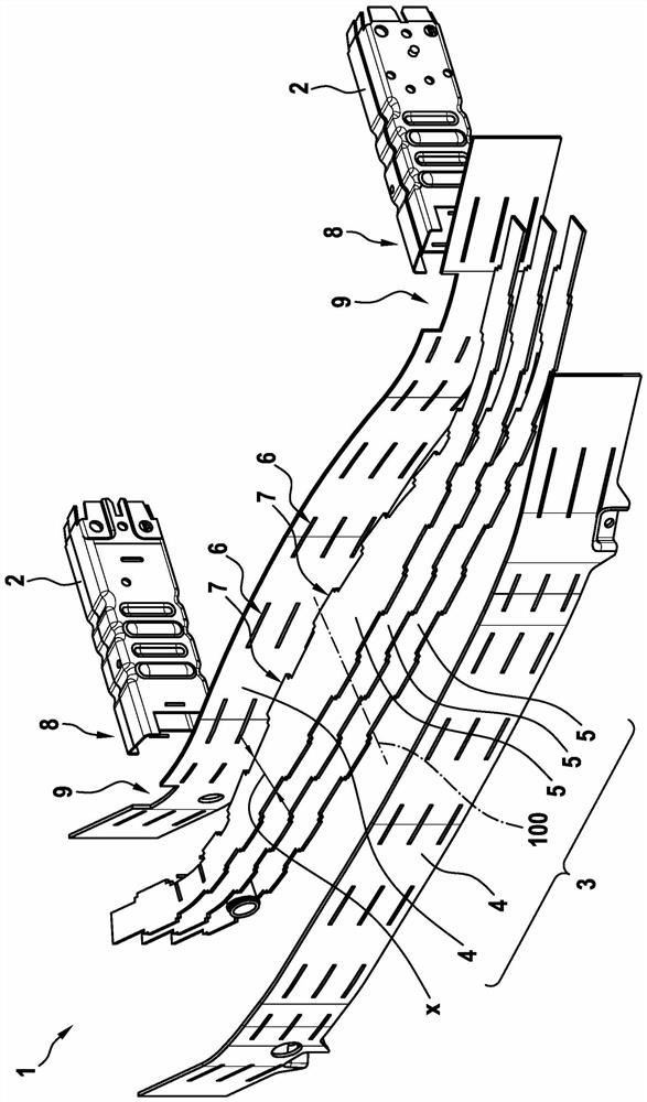
[0021] figure 2 A schematic exploded view of a bumper 1 of a vehicle 10 according to an exemplary embodiment of the invention is shown. In this case, the transverse beam 3 is configured as a combination of several strips 4 and webs 5 . The construction of the cross member 3 as a...


PUM


Abstract

The invention relates to a bumper (1) of a vehicle, comprising: at least one longitudinal beam (2); and a cross member (3) fixed to the longitudinal member (2), the cross member (3) being designed as a hollow profile body which is produced by cohesively connecting a plurality of belts (4) and webs (5).

Description

technical field [0001] The invention relates to a bumper of a vehicle. The invention also relates to a vehicle comprising such a bumper. The bumper is preferably of simple and cost-effective construction. Background technique [0002] Motor vehicle bumpers are known from the prior art. The bumper usually has a cross member which extends in the transverse direction of the vehicle. The cross member serves to absorb the forces that occur when the vehicle collides with an obstacle in order to transmit them on to the crash box. [0003] Known cross members are mostly produced in shell construction. For this purpose, the deep-drawn half-shells are typically assembled together and welded. However, manufacturing solutions with deep-drawing tools are very costly. Furthermore, the transformation of the geometry is only possible to a limited extent, since a profile bevel is always provided. Contents of the invention [0004] It is therefore the object of the present invention ...

Claims


Application Information

Patent Timeline
Patent Type & Authority Applications(China)
IPC IPC(8): B60R19/18B60R19/34
CPCB60R19/18B60R19/34B60R2019/1826B60R19/36B60R2019/1806B60R2019/186
Inventor T·汉布什M·巴特尔斯J·马加马基O·阿基辅
Owner BAYERISCHE MOTOREN WERKE AG
Why Eureka
Eureka Blog
Learn More