Continuous automatic feeding equipment of punching machine

A technology of automatic feeding and punching machine, applied in metal processing equipment, cleaning method using gas flow, feeding device, etc., can solve the problems of poor position accuracy, long process time, low processing efficiency, etc., and reduce processing defects. , The processing process is compact, and the cleaning effect is ensured

Active Publication Date: 2022-03-04
GUILIN UNIV OF AEROSPACE TECH +1
View PDF10 Cites 0 Cited by
  • Summary
  • Abstract
  • Description
  • Claims
  • Application Information

AI Technical Summary

Problems solved by technology

In the prior art, the parts to be stamped are manually placed on the processing surface of the stamping machine for stamping, which not only has low efficiency and poor positional accuracy, but also easily damages the hands of the processor, and the parts to be stamped can also be clamped by a manipulator for loading. material, which improves the accuracy and safety, but the process of using the manipulator to repeatedly load and unload the material takes a long time, the processing efficiency is low, and the use cost is high
In addition, the sundries and dust on the stamping parts before processing will cause damage to the finished stamping parts during stamping, and metal debris residues will also be left on the stamping parts after processing, which will also have a negative impact on later processing and application

Method used


Image

  • Continuous automatic feeding equipment of punching machine
  • Continuous automatic feeding equipment of punching machine
  • Continuous automatic feeding equipment of punching machine

Examples


Embodiment Construction

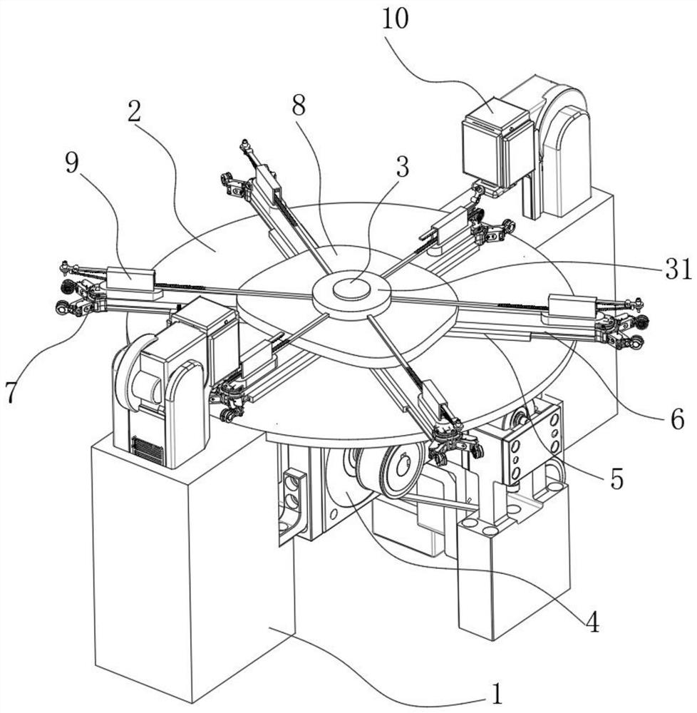
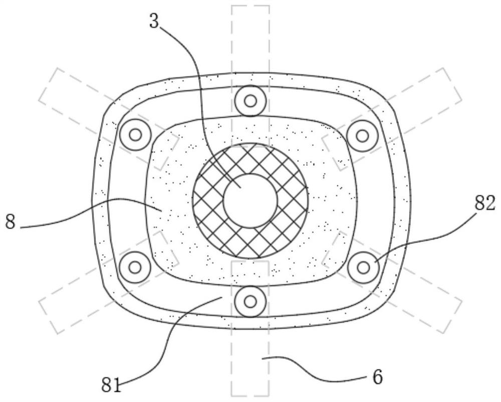
[0025] see figure 1 , in an embodiment of the present invention, a punching machine continuous automatic feeding equipment, including a bracket 1, the center above the bracket 1 is fixed with a central shaft 3, the central shaft 3 is rotatably sleeved with a turntable 2, the The turntable 2 is rotatably connected to the support 1, and the support 1 is provided with a drive device 4, and the drive device 4 can drive the turntable 2 to rotate along the edge of the turntable 2;

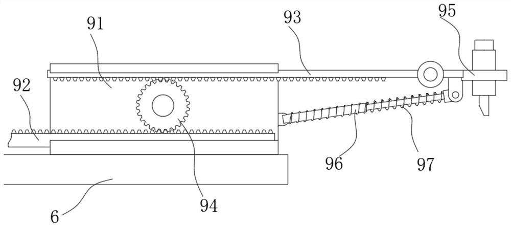
[0026] The upper circumference of the turntable 2 is evenly distributed with a plurality of guide rails 5 extending radially, each of the guide rails 5 is slidably connected with a slide bar 6, and the end of the slide bar 6 away from the center of the turntable 2 is provided with a clip. Holding device 7, the top of described holding device 7 is provided with the cleaning assembly 9 that is fixed on the slide bar 6;

[0027] At least one punching machine 10 is provided on the edge of the turntable 2 , ...


PUM


Abstract

The continuous automatic feeding equipment comprises a support, a center shaft is fixed to the center of the upper portion of the support, the center shaft is rotatably sleeved with a rotating disc, the rotating disc is rotatably connected with the support, a driving device is arranged below the support, and the driving device is connected with the rotating disc. The driving device can drive the turntable to rotate along the edge of the turntable; a plurality of guide rails extending in the radial direction of the rotary disc are evenly distributed on the circumference of the rotary disc, each guide rail is slidably connected with a sliding rod, a clamping device is arranged at the end, away from the circle center of the rotary disc, of each sliding rod, and a cleaning assembly fixed to the corresponding sliding rod is arranged above the corresponding clamping device. At least one punching machine is arranged on the edge of the rotating disc, and the working face of the punching machine faces the radial direction of the rotating disc and is within the stroke range of the clamping device. Compared with the prior art, stamping parts can be cleaned before and after stamping, machining defects are reduced, the machining procedure is compact, and the machining efficiency is high.

Description

technical field [0001] The invention relates to the technical field of punching machine auxiliary equipment, in particular to a punching machine continuous automatic feeding device. Background technique [0002] Stamping processing is a production technology that uses the power of stamping equipment to subject the sheet to deformation force and deform it, thereby obtaining product parts of a certain shape, size and performance. In the prior art, the parts to be stamped are manually placed on the processing surface of the stamping machine for stamping, which not only has low efficiency and poor positional accuracy, but also easily damages the hands of the processor, and the parts to be stamped can also be clamped by a manipulator for loading. The material improves the accuracy and safety, but the process of repeatedly loading and unloading the manipulator takes a long time, the processing efficiency is low, and the use cost is high. In addition, the sundries and dust on the ...

Claims


Application Information

Patent Timeline
Patent Type & Authority Applications(China)
IPC IPC(8): B21D43/02B21D43/10B21D43/12B21D43/14B08B5/02B08B13/00
CPCB21D43/026B21D43/10B21D43/12B21D43/14B08B5/02B08B13/00
Inventor 刘晓刚陈中敢林德民赵宏旺梁毅郭华礼
Owner GUILIN UNIV OF AEROSPACE TECH
Why Eureka
Try Eureka