
Jig conveying mechanism

A technology of conveying mechanism and jig, applied in the direction of conveyor objects, assembly machines, manufacturing tools, etc., can solve the problem of single conveying specification of the bottom shell, etc., and achieve the effect of reducing the space occupied

Pending Publication Date: 2022-03-04
广东奇创智能科技有限公司 +1
View PDF0 Cites 1 Cited by
  • Summary
  • Abstract
  • Description
  • Claims
  • Application Information

AI Technical Summary

Problems solved by technology

[0003] The purpose of the present invention is to overcome the shortage that the transfer mechanism of the existing socket assembly equipment directly drives the bottom case to move, resulting in a single delivery specification for the bottom case, and to provide a jig transfer mechanism that drives the bottom case to move by conveying the jig, so that it can pass Replace the jig to fit and assemble bottom shells of different specifications

Method used


Image

  • Jig conveying mechanism
  • Jig conveying mechanism
  • Jig conveying mechanism

Examples


Embodiment Construction

[0028] The specific embodiments of the present invention will be described below in conjunction with the accompanying drawings. In the description of the present invention, it should be noted that the orientations or positional relationships indicated by the terms "upper", "lower", "inner", "outer", "front", "back" etc. are based on the Orientation or positional relationship is only for the convenience of describing the present invention and simplifying the description, and does not indicate or imply that the referred device or element must have a specific orientation, be constructed and operated in a specific orientation, and thus should not be construed as a limitation of the present invention.

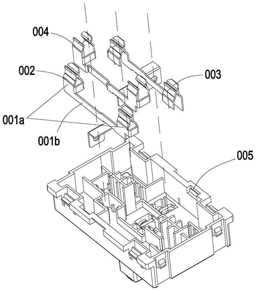
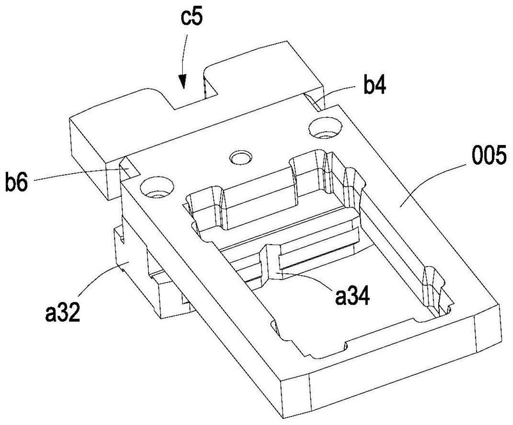
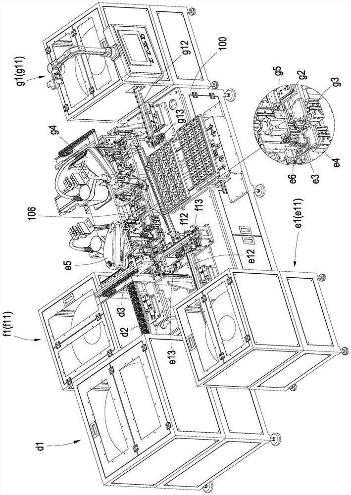
[0029] see Figure 1 to Figure 7 , this embodiment provides a jig transfer mechanism 106 applied to socket assembly equipment, and the socket assembly equipment is used to assemble metal contacts (002, 003, 004) in the bottom shell 001 of the socket, wherein the metal contacts inclu...


PUM


Abstract

The invention belongs to the technical field of socket assembly equipment, and particularly relates to a jig conveying mechanism which is provided with a jig conveying channel used for conveying a jig, a bottom shell is arranged on the jig and pokes the jig through a jig pushing device, when a poke claw pushes the jig to a next station, a limiting column abuts against the top of the poke claw, and the jig is pushed to the next station. Therefore, the shifting claw is limited to swing towards the feeding end of the jig conveying channel, and the jig is pushed towards the discharging end of the jig conveying channel. When returning to reset, the shifting claw can be in contact with the previous jig, at the moment, the shifting claw can be pushed by the jig to rotate around the rotating shaft towards one side of the discharging end of the jig conveying channel and compress the elastic reset piece, the second wedge face is movably matched with the first wedge face along with movement of the shifting claw, and therefore the shifting claw returns to reset and prepares to push the previous jig. According to the jig conveying mechanism, the shifting assembly can push the jig back and forth, so that the length of the connecting rod can be controlled, and the occupied space of the jig conveying mechanism is reduced.

Description

technical field [0001] The invention belongs to the technical field of socket assembly equipment, in particular to a jig transmission mechanism. Background technique [0002] The socket is composed of a bottom shell and a cover. The existing assembly process is generally to contact metals such as the E pole (grounding wire), N pole (connecting the neutral wire) and L pole (connecting the live wire) manually or by multiple separate devices. Insert the chip into the bottom shell, and then seal the cover on the bottom shell. This kind of assembly method has low automation, slow production efficiency, and unstable product quality. Therefore, people have developed equipment for automatic assembly of sockets. This equipment is used for The jig transfer mechanism for conveying the bottom case, and a plurality of stations arranged in sequence along the jig transfer mechanism for inserting the above-mentioned metal contacts into the bottom case, the jig transfer mechanism is provided...

Claims


Application Information

Patent Timeline
Patent Type & Authority Applications(China)
IPC IPC(8): B23P21/00B25B11/02B65G47/82B65G47/74B65G47/14
CPCB23P21/004B25B11/02B65G47/82B65G47/74B65G47/1421
Inventor 万伟鑫张海涛
Owner 广东奇创智能科技有限公司
Learn More